What is Injection Molding Gate Vestige?
In precision injection molding, a gate vestige is the physical evidence of the manufacturing process left on the part’s surface. It is the remnant that remains after the molded part is separated from its runner system. Because the gate acts as the final “valve” for molten plastic entering the cavity, it must eventually solidify and break away, meaning no molded part can ever be perfectly flush at the entry point.
A gate vestige is more than a visual blemish; it is a surface discontinuity, appearing as either a protrusion or a depression, with physical traits determined entirely by the gating strategy. Large-diameter options like sprue or edge gates often result in ragged scars that require manual trimming, while sophisticated valve gate systems leave only a subtle, circular “witness ring.” Additionally, hot runner tips can produce delicate “umbilical strands” that affect cosmetic quality, whereas tunnel or cashew gates are designed to shear automatically, leaving a functional edge typically concealed on the interior surfaces.
The Impact of Gate Vestige on Product Aesthetics and Functionality.
Aesthetic Integrity and Consumer Perception.
The most immediate impact of a gate vestige is on the visual quality of the component. Large diameter gates, such as sprue gates, necessitate mechanical degating, which inevitably leaves a prominent scar or “gate mark.” Even edge gates often leave a matte or rough patch that disrupts the surface finish.
Beyond the physical remnant, improper gating can trigger secondary surface blemishes:
- Gate Blush and Halos: High shear rates often cause dull, discolored ripples or “halos” near the entry point.
- Splay and Discoloration: Excessive shear or moisture can result in silver streaking (splay) that ruins the part’s appearance.
- Witness Lines: When gate inserts are used for easier mold maintenance, they leave a permanent circular witness line where the insert meets the cavity wall.
For “Class A” surfaces in high-end electronics or cosmetic packaging, these imperfections can “cheapen” the product, causing a loss of the “premium feel” required for brand success.
Functional Obstacles and Assembly Risks.
From a functional standpoint, an uncontrolled vestige is a dimensional hazard. Any significant protrusion can interfere with mating surfaces, preventing components from sitting flush or assembling correctly. For consumer goods with flat bases, like cups or housings, a protruding mark on the underside causes “rocking” and instability. Furthermore, these protrusions can prevent paper labels from adhering properly or cause them to wrinkle and tear.
More critically, the gate area is often the part’s structural “weak link”:
- Stress Concentration: The gate contains the highest level of residual stress and molecular orientation. Because polymer chains align at this point, the area becomes brittle and prone to cracking under impact.
- Chemical Sensitivity: This high “frozen-in” stress makes the gate region extremely vulnerable to environmental stress cracking (ESC) when exposed to solvents or chemical reagents.
Medical and Safety Compliance.
In regulated industries, the gate vestige becomes a safety concern. For medical devices or handheld consumer products, a protruding mark can be sharp enough to cause skin abrasions.
Regulatory bodies often require engineering drawings to explicitly define surfaces that must be free of any gate marks or blemishes. To meet these stringent standards, manufacturers frequently utilize valve gates. These systems provide a mechanical shut-off that ensures the most subtle witness mark possible, ensuring the part is both safe for the end-user and compliant with international safety standards.
Common Gate Types And Their Specific Vestige Characteristics.
Sprue Gate (Direct Gate).
The sprue gate allows melt to enter the cavity directly from the main runner, minimizing pressure loss. It is typically used for large, single cavity molds or deep, cup-shaped parts.
- Vestige Profile: It leaves a large, prominent protrusion that necessitates secondary manual or mechanical processing (such as cutting, sawing, or grinding).
- Engineering Risks: High residual stress and shrinkage marks are common at the entry point, which can compromise both the appearance and the structural integrity of the area.
Pinpoint Gate.
Commonly found in three plate molds or hot runner systems, these gates feature a very small diameter (0.25mm to 1.6mm).
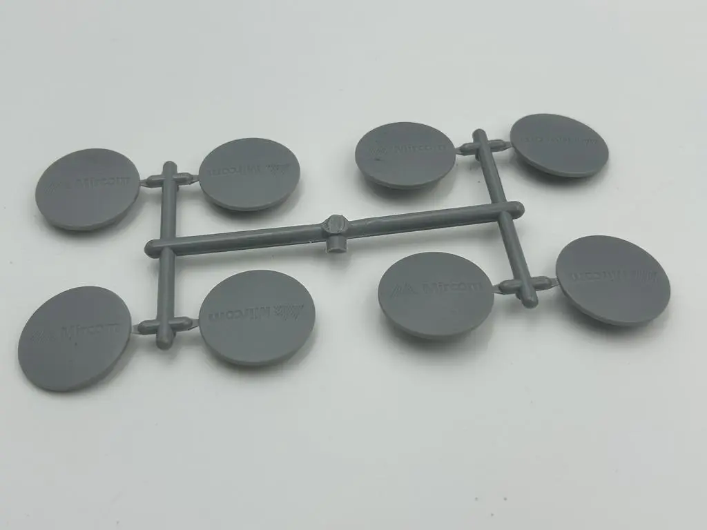
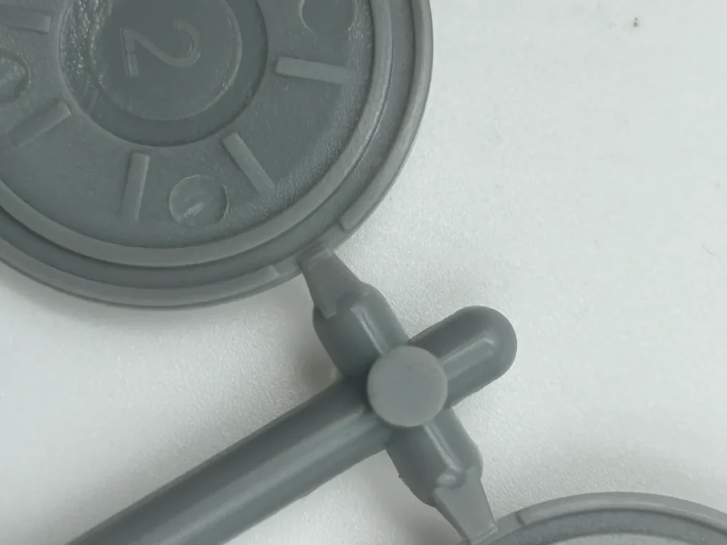
- Vestige Profile: Known for its self-degating capability, it snaps off automatically during mold opening. It leaves only a tiny, faint dot, making it the preferred choice for high-visibility consumer goods like caps and buttons.
- Engineering Risks: If the diameter is too small, high shear rates can lead to “Gate Blush” (halos) around the mark.
Edge Gate (Side Gate).
Located on the parting line, edge gates are simple to machine and cost-effective, allowing for precise control of filling rates.
- Vestige Profile: These require manual shearing, as the part remains attached to the runner system upon ejection. The resulting mark is a physical “scar” matching the gate’s cross-section, often appearing matte or rough.
- Engineering Risks: Brittle materials (like Acrylic) may suffer from micro-cracking or irregular fracturing during the trimming process.
Tunnel Gate (Submarine Gate).
The tunnel gate is positioned below the parting line, “tunneling” into the cavity wall.
- Vestige Profile: It shears automatically during ejection, significantly increasing production efficiency. The mark is usually a small circular or oval shape, often hidden on internal walls, leaving the visible exterior surface completely clean.
Valve Gate (Hot Runner Exclusive).
This advanced system uses a mechanically moved pin to physically shut off the gate exit.
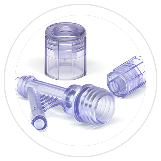
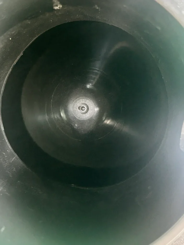
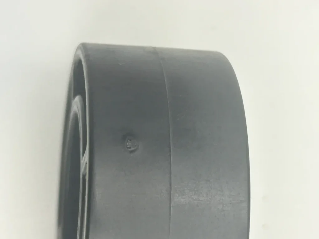
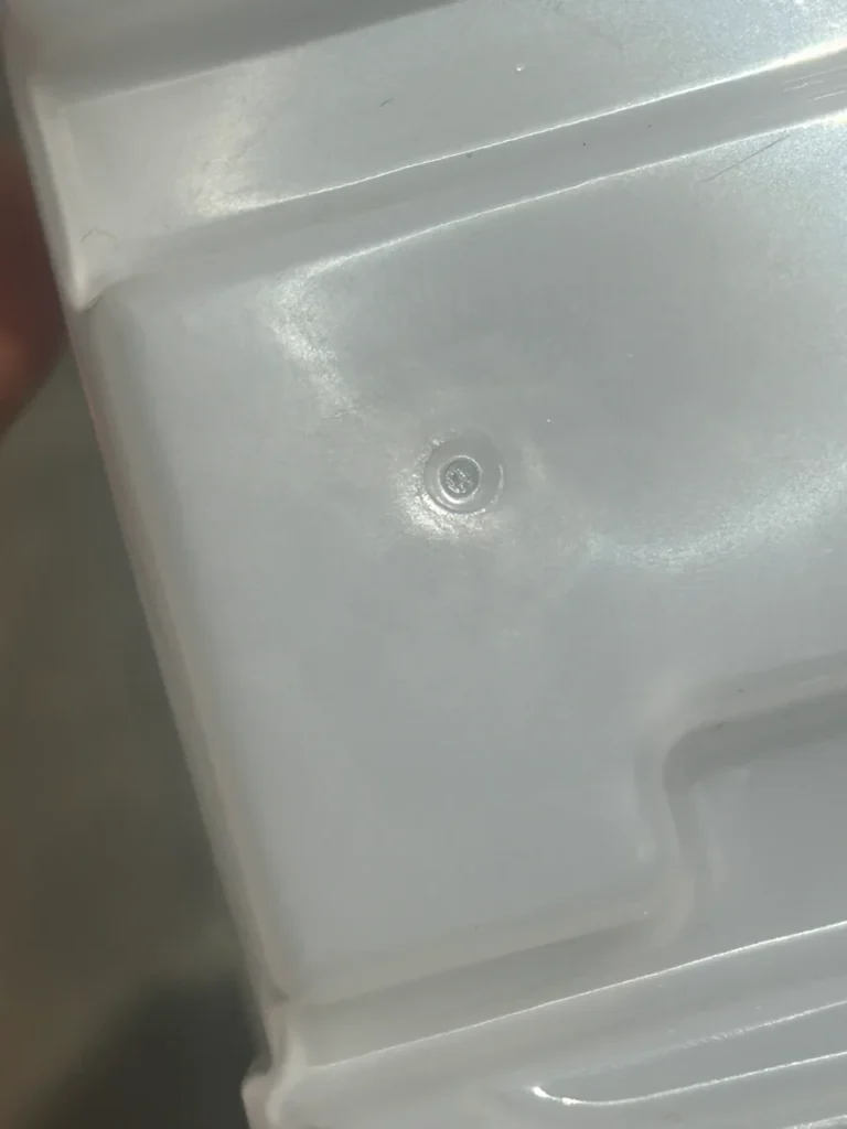
Vestige Profile: Valve gates achieve “near-zero” vestige. The only evidence is a faint, circular “witness ring,” similar to an ejector pin mark. This is the gold standard for medical devices, high-end cosmetics, and precision electronics.
Cashew Gate (Banana Gate).
A variation of the tunnel gate, the cashew gate uses a curved path to inject from the underside or back of a part.
Vestige Profile: It allows for a completely blemish-free visible surface.
Engineering Risks: Because the gate must bend significantly during ejection, brittle materials may flake or leave debris within the mold.
| Gate Type | Degating Method | Vestige Appearance | Typical Application |
| Sprue Gate | Manual/Mechanical | Large, prominent scar; requires grinding | Large parts, heavy-walled bins |
| Pinpoint Gate | Automatic (Self-snapping) | Tiny, faint dot | Aesthetic caps, small buttons |
| Edge Gate | Manual Shearing | Matte/rough physical scar | General industrial parts |
| Tunnel Gate | Automatic (Ejection) | Small circle/oval; usually hidden | High-volume production |
| Valve Gate | Mechanical Shut-off | Minimal “witness ring” | Medical, high-end electronics |
| Cashew Gate | Automatic (Curved) | No mark on visible surfaces | Aesthetics-first consumer goods |
| Fan/Film Gate | Manual Trimming | Long, narrow line (like flash) | Large, thin-walled flat parts |
| Disk/Ring Gate | Mechanical/Punching | Continuous circular witness line | Cylindrical or tube-shaped parts |
Why Does Excessive Gate Vestige Occur? Root Cause Analysis.
Design Imperfections
The physical geometry of the gate dictates how the material fractures. If the gate land length is too long (exceeding the standard 0.5mm to 1.0mm), flow resistance increases, leading to irregular breaking. Similarly, if the design lacks a sharp break point where the gate meets the cavity, the plastic will tear rather than shear. Selecting an inherently “heavy-marking” gate, like a large sprue or edge gate, for a cosmetic surface is also a fundamental design mismatch.
Processing Instability.
Even a perfectly designed mold will produce poor results if the molding parameters are out of sync.
- Thermal Control: In hot runner systems, excessive temperature at the tip causes the plastic to remain molten during mold opening, leading to “stringing” or “drooling.”
- Pressure Management: If hold time is terminated before gate “freeze-off,” the pressurized melt can backflow, causing sink marks or uneven vestiges.
- Cooling: Insufficient cooling leaves the material too soft, turning a clean shear into a ragged tear during ejection.
Tooling Wear and Maintenance.
Molds are subject to physical degradation over time. Gate erosion is particularly common when using abrasive materials like glass-filled polymers; as the sharp edges of the gate wear down and become rounded, the vestige size gradually increases. In valve-gated systems, mechanical wear or misalignment of the valve pin prevents a flush shut-off, leaving a protruding ring or “needle” mark.
Material Morphology
The inherent properties of the polymer play a significant role in how it breaks. Ductile materials (like TPE or TPU) tend to stretch during degating, leaving elongated “umbilical” strands. Conversely, brittle materials (like unmodified Acrylic) may “flake” during automatic shearing, where a small piece of the part surface breaks off with the gate, leaving a pit or crater.
| Category | Primary Issue | Impact on Vestige |
| Design | Excess Land Length | Increases breaking force; causes irregular, protruding remnants. |
| Design | Blunt Break Point | Prevents clean shearing; leads to ragged “torn” appearances. |
| Process | Excessive Tip Temp | Causes “Stringing” or “Drooling” (long plastic tails). |
| Process | Inadequate Hold Time | Leads to sink marks or hollow vestiges due to backflow. |
| Tooling | Gate Erosion | Sharp edges round off, causing the vestige to grow over time. |
| Tooling | Valve Pin Failure | Improper shut-off leaves a high-standing ring or pin mark. |
| Material | High Ductility (TPE) | Material stretches instead of snapping; leaves “umbilical” strands. |
| Material | High Brittleness | Causes “Flaking” or craters at the break point. |
Engineering Solutions: Optimizing Gate Design to Minimize Residue.
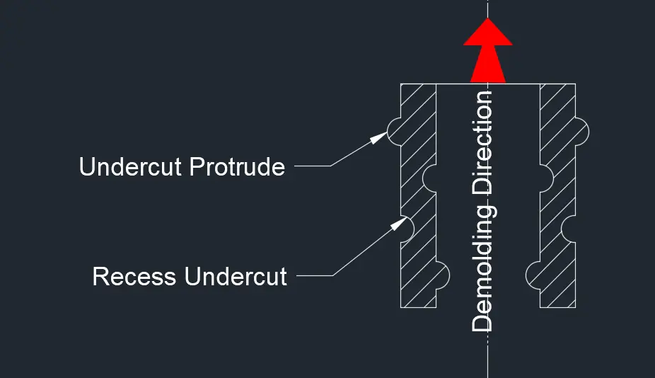
Utilizing the “Gate Dimple” and Recess Features.
One of the most effective ways to hide a vestige is to design a Gate Dimple on the surface opposite the gate. This feature creates a local “heat pool” that utilizes the material’s natural shrinkage to “suck” the protruding remnant below the nominal surface of the part.Recommended Dimensions: The dimple diameter should range between 4–10 mm.Depth (h) based on Wall Thickness (t):
If t < 0.75 mm, then h = 0.75t.If 0.75 mm < t < 1.5 mm, then h = 1.0t.
Stability Recess: For parts with flat bases (like containers), a central gate protrusion will cause “rocking.” Designing a counter-sink or recess around the gate area ensures the vestige remains flush or slightly recessed, maintaining the part’s stability.
Selecting High-Performance Gate Types.
Choosing gates with automatic shearing or precision shut-off mechanisms can drastically improve the final finish:
- Valve Gates: The premier solution for “near-zero” vestige. The mechanical pin forced-shut allows for a witness mark flush with the surface or recessed by 0.25 mm, preventing any assembly interference.
- Tunnel & Cashew Gates: These allow the gate to be hidden on internal walls or non-cosmetic ribs. For Cashew gates, it is recommended to deepen the area at the shear point to eliminate any risk of protrusion on the visible face.
- Pinpoint Gates: Ideal for three-plate molds, their tiny diameters (0.25–1.6 mm) ensure the remnant is almost invisible and requires no manual trimming.
Geometric Parameter Refinement.
Small changes in the gate’s physical dimensions can lead to significant improvements in the break-out quality:
- Shorten Gate Land Length: The land length (the distance the plastic travels through the gate’s narrowest point) should be kept between 0.13 mm and 1.0 mm. Excessive length increases pressure loss and results in an unpredictable, ragged break point.
- Sharp Break Points: Maintaining a sharp corner where the gate meets the cavity is essential. This ensures the plastic fractures cleanly at the predetermined location rather than tearing.
- D-Style Tunnel Gates: Using a D-shaped cross-section instead of a traditional cone provides a cleaner shear and reduces seal time.
Camouflage and Strategic Masking
If a vestige cannot be removed, it should be hidden:
- Structural Integration: Conceal the gate mark within decorative textures, logos, or inside the closed loops of characters (such as the center of the letters O, P, or D).
- Symmetry (The “Fake Vestige”): If a mark is unavoidable on a visible surface, consider adding a non-functional “dummy” mark symmetrically. This visual balance makes the real gate mark look like an intentional design element rather than a defect.
| Technique | Primary Benefit | Key Specification |
| Gate Dimple | Sucks vestige below surface | Diameter 4-10mm; Depth relative to wall thickness |
| Valve Gating | Near-zero witness mark | Pin shut-off flush or -0.25mm |
| Sharp Break Point | Ensures clean fracture | Sharp 90-degree edge at cavity entrance |
| Short Land Length | Reduces protrusion height | Target 0.13mm to 1.0mm |
| Gate Inserts | Consistency over time | Replaceable hardened steel inserts |
Advanced Degating Techniques To Minimize Injection Molding Gate Vestige :
Automatic “In-Mold” Degating:
Automatic degating occurs within the mold itself or during the ejection sequence. As discussed in previous sections, tunnel (submarine) and cashew gates are designed to shear the part from the runner as the mold opens or as the ejector pins move forward.
The Benefit: It eliminates secondary labor entirely and ensures a consistent cycle time, which is vital for high-volume automotive or consumer electronics projects.
Robotic Degating (Post-Molding Automation).
Modern injection molding company frequently utilize gantry or six-axis robots to bridge the gap between manual and in-mold methods.
- Mechanism: Robots equipped with specialized End-of-Arm Tooling (EOAT) extract the entire sprue and part tree. While in transit to the conveyor or unloading station, integrated pneumatic cutters on the EOAT perform the degating.
- The Benefit: This combines the precision of a mechanical cut with the speed of automation, ensuring that the part is never dropped and that the gate is trimmed at the exact same angle every time.
Ultrasonic Degating: High-Frequency Separation.
For high-precision or rigid parts where mechanical cutting might cause stress whitening or cracking, ultrasonic technology offers a non-contact alternative.
- Mechanism: This technique applies high-frequency ultrasonic vibrations to the runner system. These sonic cycles create localized fatigue at the narrowest point—the gate—until the part “vibrates” free.
- Material Constraints: It is exceptionally effective for rigid materials like Polycarbonate (PC) or Acrylic (PMMA). However, it is generally unsuccessful with soft or elastomeric plastics (like TPE or TPU), as these materials tend to absorb the vibrations rather than fracturing.
| Technique | Efficiency | Consistency | Best Material Fit |
| Manual | Low | Low (Human dependent) | Complex geometries, low volume |
| In-Mold (Tunnel) | Very High | High | High-volume, non-cosmetic edges |
| Robotic (EOAT) | High | Very High | Precision parts requiring mechanical trim |
| Ultrasonic | High | Excellent | Rigid, brittle, or medical-grade plastics. |
Conclusion:
At Qlution Mold, we understand that for high-precision industries,from medical devices to premium consumer electronics.even a micron-level protrusion can be the difference between a high-quality component and a rejected batch. Our engineering team specializes in scientific molding and advanced tool design to ensure your parts meet the most stringent “Class A” surface standards.
Ready to eliminate unsightly gate marks from your next project?
Contact the experts at Qlution Mold today for a comprehensive DFM (Design for Manufacturing) analysis. Let us help you optimize your mold design for flawless, precision-engineered results.