1. What Is an Undercut in Injection Molding?
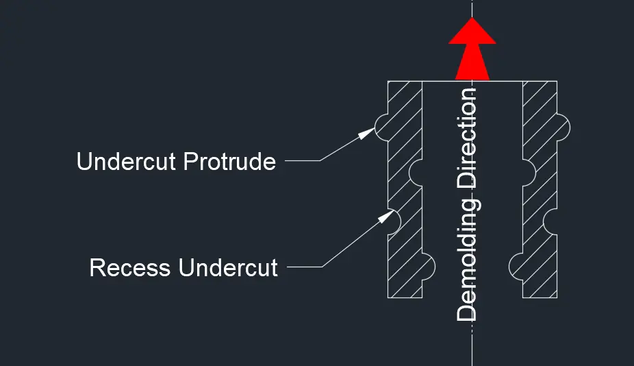
At its most precise, an undercut is any projection or recess in a part design that is perpendicular to the angle of draw: the direction in which the mold opens. In injection molding terms, it represents a positive or negative change in the inner or outer contour of a part that prevents the mold from releasing the part in a straight line.
Several technical descriptions are worth understanding, because each highlights a different aspect of the problem:
Reverse draft:
An undercut is sometimes described as a reverse or negative draft: a protuberance or indentation that runs counter to the taper needed for clean ejection, requiring either a split mold or internal inserts to free the part.
Ejection interference:
From a functional standpoint, an undercut is any feature that physically interferes with the ejection of the part from the mold. This is the definition that matters most during DFM review.
Holes and impressions in sidewalls:
Any hole or recess that passes through a sidewall or into a vertical section of a part qualifies as an undercut, because the mold steel forming that feature cannot withdraw in the opening direction.
Because undercuts break the simple up and down motion of mold opening and ejection, they require additional mechanisms like slides, cams, lifters that add cost and complexity. Depending on the geometry, undercuts typically increase tooling cost by 15% to 30%. In parts with undercuts on multiple axes or with deep internal geometry, that figure can reach 100%. Cycle time increases, wear prone components are added to the mold, and long term maintenance burden rises. None of this means undercuts should always be avoided many are functionally necessary. But every undercut that remains in a design at the mold-cutting stage should be there for a deliberate reason.
2. Why Engineers Miss Undercuts During Design
Here’s what I’ve observed after reviewing hundreds of RFQ submissions: engineers working in CAD rarely think in terms of mold opening direction. They’re focused on function: will this snap-fit hold? Will this groove seal properly? The manufacturing implications come second, and often aren’t considered until the DFM report arrives.
A few patterns come up repeatedly.
Snap-fits copied from sheet metal references. Snap-fits in injection molded parts need to be oriented so the locking surface is accessible in the mold draw direction: or they need a side action. When designers copy snap-fit geometry from a sheet metal part, they often create undercuts that require costly sliders, when a simple reorientation would have solved the problem.
Side holes added without parting line consideration. A hole on the side of a housing seems trivial. But if it’s perpendicular to the mold pull direction, it’s an undercut. Rotating that hole even a few degrees, or relocating it to a surface parallel to the draw direction, can sometimes eliminate the side action entirely.
Threads modeled as true helical geometry. Modeled threads look correct in CAD but create complex undercuts in the mold. In many cases, the thread isn’t actually necessary: a heat-staked insert, a push-on boss, or a self-tapping screw hole does the job with less tooling complexity and better long term reliability.
Recessed logos and text on angled surfaces. Text recessed into a surface that isn’t parallel to the draw direction becomes an undercut across every character. Embossed text on a flat, properly drafted surface avoids this entirely.
The first principle of DFM for undercuts is this: before deciding how to handle an undercut, ask whether it can be eliminated. Eliminating an undercut through geometry is always cheaper than building a mechanism to accommodate it. I’d estimate that 30–40% of the undercuts flagged in DFM reviews I’ve conducted could have been eliminated with a minor design change, had the engineer been thinking about mold direction from the start.
3. External vs. Internal Undercuts: Key Differences
Understanding the distinction matters because the solution set is different: and so is the cost.
External Undercuts
External undercuts sit on the outside of the part, accessible from the mold’s exterior. Side holes, lateral slots, external snap hooks, and external grooves are the most common examples.
These are generally more straightforward to address. The mold’s moving components: slides, split cavity jaws: can reach external features from outside the part envelope. Parting line adjustment alone can resolve many external undercuts at zero additional cost.
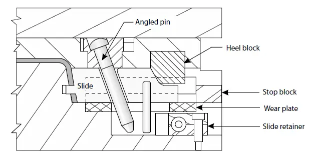
For external undercuts that genuinely require a mechanism, side actions (sliders) are the standard solution. A slider is driven by an angled cam pin (horn pin) on the A-side, which converts the vertical mold-opening motion into lateral travel. The cam pin angle is typically between 10° and 25°: below 10° the travel distance becomes impractically short; above 25°, the lateral force on the cam pin increases to a point where galling and accelerated wear become real risks.
For very large external undercuts: deep recesses, large external ribs, or complex surface textures across wide areas: split cavity molds (also called jaws or clam-shell molds) split the cavity itself into two or more sections that open laterally before the main mold opens. These are more expensive but sometimes the only practical option for complex external geometry.
Internal Undercuts
Internal undercuts exist inside the part geometry: threads on the interior of a cap, inward-facing snap fits inside a housing, recessed clips inside a boss. These are harder to handle because no mold action can reach them from the outside.
The key difference in cost and complexity: external undercuts solved with sliders are generally a known, predictable engineering problem. Internal undercuts solved with lifters or collapsible cores involve more constrained geometry, tighter tolerances, and more coordination in the ejection system.
As a practical rule: if you have a choice between placing a functional feature on the outside or inside of a part, external placement is almost always more mold friendly.
4. 5 Solutions for Injection Molding Undercuts
There is no single right answer. The correct approach depends on the geometry, production volume, material, and budget. Here’s how I think through each option.
Parting Line Adjustment
Moving the mold’s parting line so it intersects with the undercut feature, allowing it to be formed by one mold half instead of requiring a side action.
Best for external features: side holes, slots, snap hooks: where the geometry can be bisected by the parting line without affecting function or appearance. Cost impact is zero; this is a mold design decision, not an additional component. The limitation is cosmetic: the parting line leaves a witness mark on the part surface. On visible or sealing surfaces, this may be unacceptable.
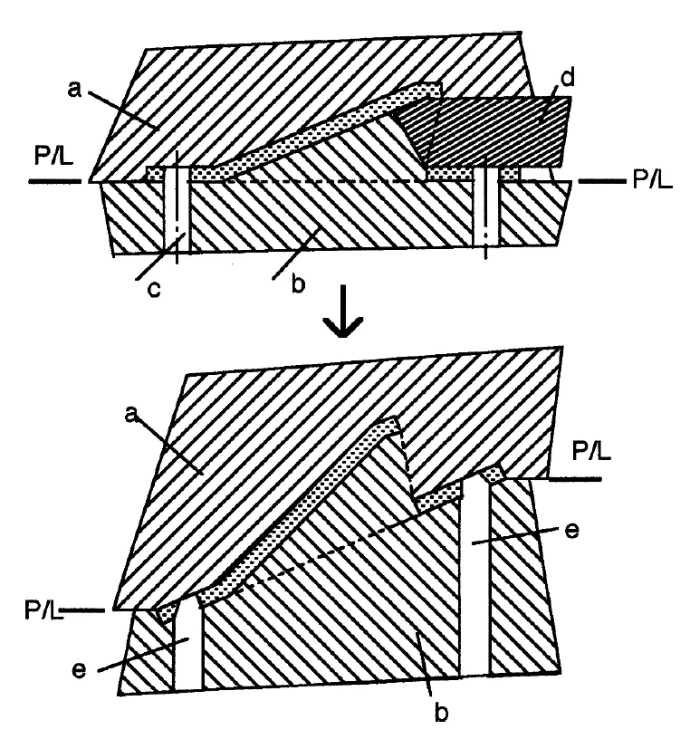
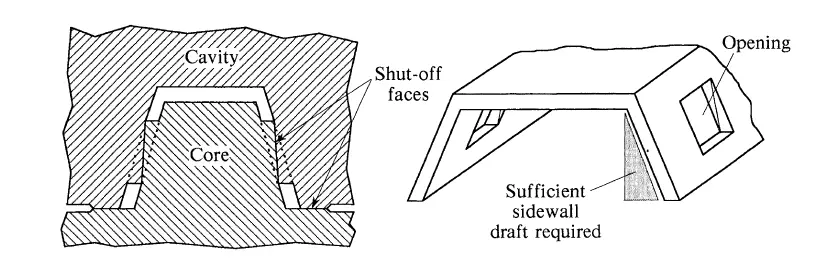
Shutoff (Bypass)
A piece of mold steel that reaches through the part geometry to close off a region, forming the undercut without a side action. One face of mold steel contacts the opposing face: a shutoff.
Best for internal snap-fits, cantilever clips, and through-holes in walls that run roughly parallel to the draw direction. The concept is simple: instead of adding a side action, you remove material from the part design around the undercut so the mold can access it directly. Cost impact is low: it’s a mold design change, not a moving component.
The critical requirement is draft on the shutoff surfaces. If shutoff faces are parallel, they drag against each other on every cycle and wear prematurely. Sufficient shutoff angle is a detail that separates experienced mold designers from inexperienced ones.
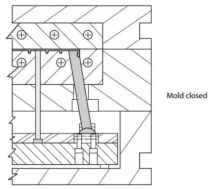
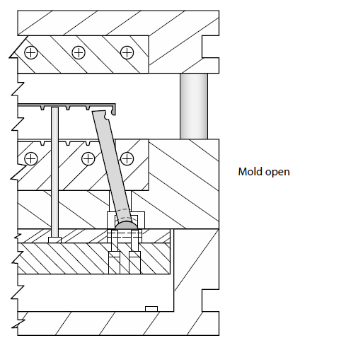
Side Action (Slider)
A movable mold component that travels laterally to clear the undercut before the mold opens, driven by a cam pin on the A-side.
This is the workhorse for external undercuts that can’t be resolved by parting line adjustment or shutoff. Each slider adds engineering, machining, and ongoing maintenance. Cost per slider varies with complexity, but budgeting $1,000–$3,000 per slider as a rough guide is reasonable for most standard mechanisms. Multiple sliders multiply the cost and can create spatial conflicts in the mold base.
Lifter (Jiggle Pin)
A mold component mounted on the ejector plate that travels at an angle during ejection: simultaneously pushing the part out and withdrawing from the internal undercut. Lifters are the primary solution for internal undercuts that sliders can’t reach.
Lifter angle is typically 5°–15° from vertical. The angle determines how much lateral travel the lifter achieves per unit of ejection stroke: steeper angles give more lateral travel but also more lateral force on the ejector plate. Very deep internal undercuts may exceed what a single lifter stage can clear.
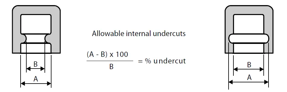
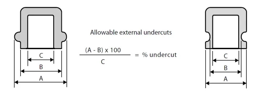
Forced Ejection (Bump-Off / Stripping)
The part is ejected straight out of the mold, flexing momentarily over the undercut, then returning to its designed geometry.
This works for shallow undercuts in flexible materials: PP, PE, TPE, soft PVC. The calculation criteria: undercut depth should generally be less than 5% of the feature diameter. For rigid materials like PC and ABS, the limit tightens to around 2.5%; for unfilled nylon, it can reach 6–10%. The undercut edge must have a lead-in angle of 30°–45° to guide the part over the steel without tearing, and the surface should be highly polished to minimize drag.
Temperature matters here too. During forced ejection, the part needs to retain enough heat (typically above the glass transition temperature) to deform elastically: but not so much that it deforms permanently. Getting this right requires tuning the cooling circuit and ejection timing, not just the geometry.
For rigid or glass-filled materials, forced ejection is not an option. Attempting it causes stress whitening, cracking, or permanent deformation.
Collapsible Core
A segmented core that collapses inward during ejection, allowing it to clear 360° continuous internal undercuts: threads, O-ring grooves, internal snap rings. Used when internal geometry is too complex or too deep for a lifter to clear.
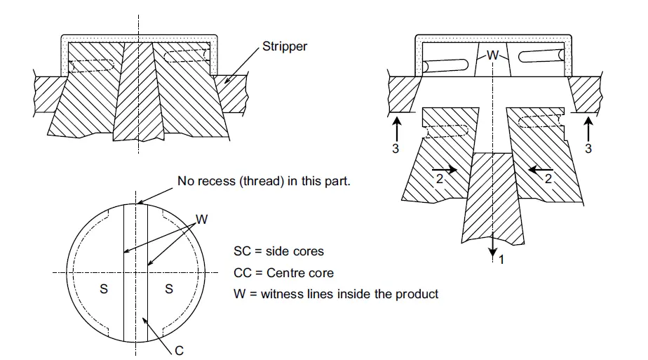
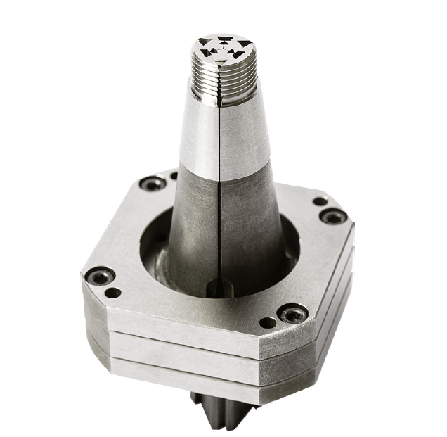
Collapsible cores are precision components and represent a significant tooling investment. They’re most justified in high-volume applications where the alternative (secondary machining of the thread, or assembly of a separate threaded insert) would be more expensive over the tool’s lifetime.
5. How to Choose the Right Solution: A DFM Decision Tree
When reviewing your own design before sending an RFQ, work through this sequence.
Step 1: Can you eliminate it? Can the undercut feature be redesigned without losing function? A different snap-fit orientation, a repositioned hole, a heat-staked insert replacing a molded thread, embossed text instead of recessed: sometimes the undercut isn’t necessary at all. This step costs nothing.
Step 2: Can a parting line adjustment or shutoff resolve it? If the feature must stay, can the parting line bisect it? Can a shutoff reach the geometry without a side action? These are zero-cost tooling solutions. If yes, stop here.
Step 3: Is forced ejection viable? Is the material flexible? Is the undercut depth within the 5% (or 2.5% for PC/ABS) threshold? Is a 30°–45° lead-in angle achievable? If all three are yes, forced ejection is worth discussing with your supplier: and it adds nothing to tooling cost.
Step 4: Lifter or slider? External undercut → slider. Internal undercut → lifter. Internal undercut too deep or geometrically complex for a lifter → collapsible core.
Step 5: Apply the Steel Safe principle. When sizing any undercut mechanism, design the steel conservatively: shallower undercut, tighter tolerance. Steel can be removed later to deepen an undercut. Steel cannot be added back. Starting steel-safe means you have room to tune after first shots without cutting a new component.
Step 6: Is the part worth redesigning? If an undercut analysis reveals that a small part needs four sliders on three axes, sometimes the right answer is splitting the design into two parts that assemble together. The added BOM complexity is often cheaper than the tooling required to make a single heavily undercut part.
The earlier you work through this sequence, the less expensive the outcome. A 30-minute DFM conversation before steel is cut routinely prevents weeks of revision after it.
6. Real-World Example: Resolving Three Undercuts Before Steel Is Cut
A customer submitted a housing design for a handheld medical device: POM material, roughly 80mm × 50mm × 30mm. The design had three features flagged in our DFM review:
- A snap-fit latch on the side wall (external undercut)
- An internal thread boss intended for a metal insert
- Two small side holes for a connector port
Here’s how each was resolved before any steel was cut.
Snap-fit latch: The parting line was repositioned to bisect the latch geometry. The witness mark landed on a non-visible interior edge. No slider was needed, and the tooling cost stayed exactly where it started.
Thread boss: The customer agreed to switch to a heat-staked insert in a straight-pull boss. The molded thread was eliminated entirely. Tooling cost dropped, assembly became faster, and thread stripping: a known failure mode in POM: was removed from the risk register.
Side holes: These were genuine side actions. The connector geometry couldn’t be redesigned without affecting the mating component, so two small sliders were added. The customer understood the tradeoff and accepted it.
Net result: three undercuts flagged, two eliminated at zero tooling cost, one handled with a standard mechanism. This is a typical outcome when DFM is done before steel is cut rather than after.
The thread boss resolution is worth highlighting specifically. The original intent was to create a reusable threaded connection. The heat-staked insert achieved the same function with better pull-out strength, no undercut in the mold, and faster cycle time. The “better” design from a CAD perspective was actually worse from every manufacturing and functional angle. This is the kind of thing that only surfaces in a real DFM conversation: not in a quoting form.
7. Undercut Design Guidelines: Quick Reference
A consolidated set of rules to check before submitting any design with potential undercuts.
Angle limits for cam pins (sliders): Keep between 10° and 25°. Below 10°, slide travel is insufficient for most undercut depths. Above 25°, lateral cam forces increase substantially, accelerating wear on the horn pin and slide.
Forced ejection depth limits: Less than 5% of feature diameter for PP/PE/TPE/unfilled nylon. 2.5% or less for PC and ABS. Always include a 30°–45° lead-in chamfer on the undercut edge, and specify high polish (SPI A-2 or better) on the corresponding mold surface.
Shutoff draft: Any shutoff surface needs positive draft: never parallel. Zero-draft shutoffs will gall and wear within a few thousand cycles.
Steel safe first: When dimensioning undercuts, start conservative. It’s straightforward to remove steel and deepen an undercut after first shots. Adding steel back means welding and remachining.
Witness marks: Every moving component: slider, lifter, split cavity jaw: leaves a parting line or witness mark on the part surface. Identify these early and confirm they land on acceptable surfaces. On sealing faces, Class A surfaces, or mating interfaces, a witness mark may be a functional failure, not just cosmetic.
Vacuum stiction (stiction): Deep undercuts can create a vacuum between the part and the mold during ejection, causing the part to deform or stick: even when the geometry itself is technically demolable. On deep-draw features, air poppets (small spring-loaded air valves in the mold) are used to break the vacuum at ejection. If your part has deep pockets or enclosed geometry, ask your mold maker whether air venting is designed into the tool.
Flash risk at slider/lifter interfaces: The mating faces between a slider and the mold block must be held to tight tolerances. Under injection pressure, any gap at these interfaces will produce flash. Heel blocks (locking wedges behind the slider) are standard practice to hold the slider face against cavity pressure. Confirm your tool includes them: especially on high-pressure materials like glass-filled nylon or PC.
Multi-axis undercuts: A part requiring sliders on three or more sides is a mold design problem as much as a manufacturing cost problem. There may not be enough space in the mold base to fit all mechanisms, and the cycle time impact compounds with each additional action. If a design review reveals multi-axis undercuts, treat that as a flag to revisit the part architecture: not just the tooling.
Conclusion:
Undercuts are a normal part of injection mold design. Most functional parts have at least one. The difference between a design that quotes cleanly and one that triggers a long DFM revision cycle usually isn’t the presence of undercuts: it’s whether the engineer thought about them before submitting.
The decision hierarchy is simple: eliminate first, then use the cheapest mechanism that works, and always know what you’re trading off. A parting line adjustment costs nothing. A shutoff costs little. A slider adds real money. A collapsible core adds significant money. Multi-axis slider configurations sometimes cost more than the alternative of splitting the part.
If this article raised questions about a design you’re currently working on, we’re happy to take a look. Submit your files for a DFM review and we’ll walk through any undercut issues: and the options for resolving them: before you commit to tooling.