What Injection Molding Shrinkage Is?
Injection molding shrinkage is the volumetric reduction of a polymer melt as it cools from processing temperature to ambient conditions. This contraction, typically expressed as a percentage of the mold cavity dimension, results from thermal expansion differences between the molten resin and the steel mold. For semi-crystalline materials like POM or PA66, shrinkage ranges from 1.5% to 3.0%, while amorphous polymers such as PC or ABS exhibit lower values between 0.4% and 0.7%.
The mechanism involves three stages: in-mold cooling shrinkage (from melt temperature to ejection), post-ejection free shrinkage (to ambient), and long-term crystallization shrinkage (over days or weeks for semi-crystalline grades). The total shrinkage rate is governed by:
- Polymer structure: Crystallinity percentage directly correlates with shrinkage magnitude higher crystallinity yields greater contraction.
- Mold temperature: Elevated mold temperatures slow cooling, allowing more complete crystallization and higher shrinkage (up to 0.2% increase per 10°C rise for PP).
- Wall thickness: Thicker sections cool slower, increasing volumetric shrinkage a 3 mm wall may shrink 0.8% more than a 1 mm wall in HDPE.
- Holding pressure: Higher pack pressure (e.g., 80% of injection pressure) reduces shrinkage by compensating for material contraction during solidification.
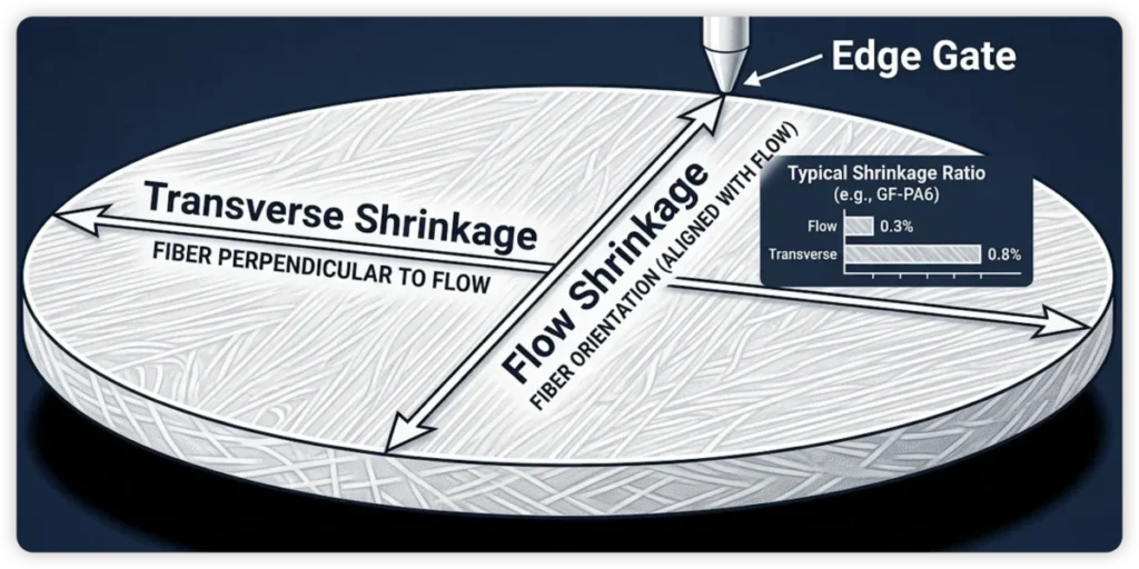
Shrinkage is anisotropic in fiber reinforced materials; glass fiber orientation causes greater contraction along the flow direction (e.g., 0.3% vs. 0.8% perpendicular in 30% GF-PA6). For precision tooling, mold cavities are typically oversized by the calculated shrinkage rate plus a safety margin of 0.05–0.10% to account for batch-to-batch resin variations. The standard test method (ASTM D955) measures shrinkage 48 hours post-molding on a 100 mm bar under controlled ambient conditions.
How To Measure Injection Molding Shrinkage Rate?
The shrinkage rate of a molded part is calculated using the formula: S = (Dmold – Dpart) / Dmold × 100%, where S is the shrinkage percentage, Dmold is the mold cavity dimension at room temperature (typically 23°C), and Dpart is the corresponding part dimension measured 24-48 hours post-molding under standard conditions (23°C, 50% relative humidity).
For accurate calculation:
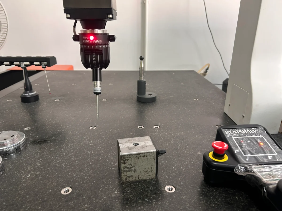
- Measure Dmold using a coordinate measuring machine (CMM) with an accuracy of ±0.001 mm, accounting for thermal expansion of the mold steel (e.g., P20 tool steel coefficient: 11.5 × 10⁻⁶/°C).
- Condition parts for at least 24 hours at 23°C ± 2°C to allow post-mold crystallization and stress relaxation, especially for semi-crystalline polymers like POM or PA66.
- Use a micrometer or CMM for Dpart measurement, averaging 5-10 samples from a stable molding cycle (after 20+ cycles of steady-state processing).
Key variables influencing shrinkage rate calculation:
- Material-specific shrinkage data: e.g., unfilled ABS: 0.4-0.7%, 30% glass-filled PBT: 0.2-0.5%, HDPE: 1.5-3.0%.
- Melt temperature: A 10°C increase can raise shrinkage by 0.05-0.15% for amorphous polymers.
- Hold pressure: Increasing hold pressure by 10 MPa reduces shrinkage by approximately 0.1% for semi-crystalline materials.
- Mold temperature: For PC, a 20°C mold temperature increase reduces shrinkage by 0.05-0.1%.
For multi-cavity tools, calculate shrinkage per cavity individually to account for flow imbalance. Corrective actions: if calculated shrinkage exceeds ±0.05% of target, adjust hold pressure or cooling time, then recalibrate mold dimensions via EDM or machining.
How To Verify Injection Molding Shrinkage Rate?
Shrinkage rate is calculated using the mold cavity dimension minus the final part dimension, divided by the mold cavity dimension, multiplied by 100. For precise measurement, use a calibrated coordinate measuring machine (CMM) on parts conditioned for 48 hours at 23°C and 50% relative humidity per ISO 294-4 or ASTM D955.
- Mold cavity measurement: Record cavity dimensions at 20°C ±1°C using a CMM with 0.001 mm resolution. Measure in flow direction and cross-flow direction separately, as shrinkage is anisotropic.
- Part measurement: After ejection, cool parts on a flat surface for 24 hours minimum. Measure at the same temperature and humidity as cavity. Avoid measuring near gate or weld lines; use three points per dimension and average values.
- Calculation formula: Shrinkage rate (%) = [(Cavity dimension – Part dimension) / Cavity dimension] × 100. For example, a 100.00 mm cavity producing a 99.20 mm part yields 0.80% shrinkage.
- Critical variables: Repeat measurements for at least 5 consecutive cycles to account for process stabilization. Report shrinkage as a range (e.g., 0.75%–0.85%) due to melt temperature, injection pressure, and cooling rate influences.
- Material-specific standards: For semi-crystalline resins (e.g., POM, PA), allow 48-hour conditioning due to post-mold crystallization. For amorphous resins (e.g., PC, ABS), 24 hours suffices.
The most reliable way to verify your shrinkage compensation is to run actual shots. Our prototype tooling service gets you real parts in 7–15 days.
Most Common Misconception About Injection Molding Shrinkage Rate
The “Single Number” Fallacy
The Myth: There is a static, universal shrinkage percentage for any given material.
The Reality: Shrinkage is a system property, not just a material one. It varies across a single part based on localized temperature history, pressure gradients, and cooling rates.
Over-Reliance on Supplier Data Sheets。
The Myth: Data sheet averages are exact blueprints for mold design.
The Reality: Lab-tested data (usually on 1/8-inch bars) rarely matches complex real-world geometries. Actual shrinkage can deviate by over 100% from the published minimums depending on your specific wall thickness and gating.
The “Isotropic” Assumption.
- The Myth: Plastic shrinks equally in all directions.
- The Reality: Most resins, especially fiber reinforced ones, exhibit anisotropic shrinkage. Fibers restrict shrinkage in the flow direction while allowing much higher contraction in the transverse direction.
The “Immediate Stability” Error
The Myth: Parts are dimensionally stable as soon as they reach room temperature.
The Reality: Shrinkage is an ongoing process. Post-mold shrinkage can continue for 24 to 48 hours, and for semi-crystalline polymers like Nylon or Acetal, dimensions may continue to drift for weeks.
Attempting to “Process Around” Structural Flaws.
The Myth: You can fix warpage caused by uneven wall thickness just by adjusting injection pressure.
The Reality: Non-uniform wall thickness is the primary cause of warpage. No amount of packing pressure can perfectly compensate for the internal stresses created by poor part design.
Gate and Packing Mistakes
Premature Pressure Release: Releasing packing before the gate solidifies allows plastic to backflow, causing a sudden jump in shrinkage.
Undersized Gates: A gate that is too thin freezes instantly, preventing proper packing and leading to excessive, uncontrolled shrinkage.
The “50% Rule” Myth: Blindly setting packing pressure to 50% of injection pressure is a guess. Optimal pressure is dictated by geometry, not a fixed ratio.
Neglecting the “Steel Safe” Mold Design.
The Myth: Machine the mold to exact predicted dimensions on the first try.
The Reality: Because shrinkage is never 100% predictable, the best practice is to remain “Steel Safe.” Making cavities slightly undersize and cores slightly oversize allows for precision fine-tuning by removing metal, which is far cheaper than welding or scrapping a tool.
Blind Faith in Computer Simulations (CAE).
The Myth: If the software says it will work, it will work.
The Reality: “Garbage in, garbage out.” Simulations often assume perfect venting and ideal conditions. A simulation is a powerful tool for trend analysis, but it should never replace the seasoned judgment of an experienced mold engineer.
“The most accurate way to measure real shrinkage rates is through prototype injection molding with production-grade resins.”
Hdpe Injection Molding Shrinkage Rate
HDPE injection molding shrinkage rate typically ranges from 1.5% to 4.0%, depending on crystallinity, wall thickness, and processing conditions. Semi crystalline structure causes higher volumetric contraction than amorphous polymers. Key factors: mold temperature (20–60°C) reduces shrinkage at lower end; melt temperature (180–280°C) increases shrinkage with higher values; injection pressure (600–1500 bar) minimizes shrinkage through packing. Wall thickness over 3 mm elevates shrinkage due to slower cooling and greater crystallinity. Isotactic HDPE grades exhibit 2.5–3.5% shrinkage, while branched grades reach 1.5–2.5%. Use mold shrinkage design allowances of 0.015–0.035 mm/mm for tooling compensation. Post-molding annealing at 120°C for 2 hours reduces residual shrinkage by up to 30%.
Soft PVC Injection Molding Shrinkage Rate
Soft PVC (plasticized PVC) exhibits a shrinkage rate of 1.5% to 3.0%, significantly higher than rigid PVC (0.2%–0.6%) due to plasticizer content and molecular orientation. Key factors:
- Plasticizer concentration: Increasing plasticizer (e.g., DOP, DINCH) from 30 to 60 phr raises shrinkage by 0.5%–1.0% per 10 phr increment, as plasticizers disrupt polymer chain packing.
- Mold temperature: Lower mold temperatures (20–30°C) reduce shrinkage to 1.5%–2.0%, while higher temperatures (40–60°C) increase it to 2.5%–3.0% due to slower cooling and greater crystallinity.
- Wall thickness: Thin walls (1–2 mm) shrink 2.5%–3.0%; thick sections (4–6 mm) shrink 1.8%–2.2% due to differential cooling rates and stress relaxation.
- Injection pressure: Hold pressure of 40–80 MPa minimizes shrinkage by 0.3%–0.5% compared to 20–40 MPa, reducing volumetric contraction during packing.
- Post-mold aging: Soft PVC continues shrinking 0.2%–0.5% over 24–48 hours as plasticizer migration and residual stress equilibrate.
For precision parts, compensate with mold cavity dimensions scaled by +2.2% to +2.8% (median shrinkage) and implement controlled cooling cycles (30–45 seconds) to stabilize dimensions. Shrinkage anisotropy is negligible (<0.2% difference) in flow vs. cross-flow directions due to low polymer orientation in soft grades.
Best Practice With Injection Molding Shrinkage Rate:Beyond The Date Sheet
Adopt a “Steel Safe” Design.
Expert designers never rely solely on “average” rates. We design tools to be “Steel Safe”,machining cavities slightly undersize and cores slightly oversize. This allows us to precisely remove metal to hit targets, avoiding the high cost of welding or scrapping a tool.
Conduct a Scientific Gate Freeze Study.
Dimensional stability is impossible without mastering the packing phase. We perform a Gate Freeze Study to stabilize part weight. If pressure is released before the gate freezes, molten plastic flows back, causing uncontrolled shrinkage.
The 24-48 Hour Measurement Rule.
Parts continue to change shape long after ejection. Semicrystalline molecules continue to rearrange as they crystallize at room temperature. We wait for thermal and molecular equilibrium before performing critical inspections.
Gating for Reinforced Resins
When using glass-filled resins, we place gates in a way which is able to manage directional shrinkage. By controlling fiber orientation, we mitigate the inherent warpage risks of anisotropic materials.
Conclusion:
Understanding injection molding shrinkage is not just about memorizing formulas; it’s about mastering the variables that dictate the final quality of your product. As we’ve explored, factors ranging from polymer crystallinity to gate location and cooling rates all play a critical role in how a part achieves its final dimensions.
Key Takeaways for Your Next Project:
- Material Matters: Always distinguish between amorphous and semi-crystalline resins early in the design phase.
- Account for Anisotropy: If you are using fiber-reinforced materials, remember that shrinkage will differ between the flow and transverse directions.
- Standardize Testing: Always measure dimensions under controlled conditions (e.g., 24-48 hours post-molding) to ensure data consistency.
At Qlution Mold, we don’t just “guess” the shrinkage rate. We combine years of tooling experience with scientific molding principles to ensure that every cavity is machined with the precision required for high-performance applications.
Are you dealing with unpredictable part dimensions or warping issues? Contact our engineering team today to discuss your project requirements. We’re here to help you bridge the gap between design intent and manufacturing reality.