In this article, we will walk you through the complete insert molding process, core design guidelines, and critical engineering considerations ,so you can design better parts, avoid costly failures, and choose the right manufacturing partner.
What Is Insert Molding and How Does It Work?
Insert molding is a manufacturing process in which a pre-formed component ,most commonly a metal insert is placed into an injection mold cavity and permanently encapsulated by molten thermoplastic. The result is a single, integrated part that combines the mechanical strength of metal with the design flexibility of plastic.
The core business value is straightforward: by integrating inserts directly during the molding cycle, manufacturers eliminate secondary assembly operations such as gluing, welding, or mechanical fastening — reducing total installed cost and improving part reliability.
The 5 Step Insert Molding Process
Step 1: Component Loading.
The insert is placed into the open mold cavity ,either manually by an operator or automatically via gantry or six-axis robots. High-volume production relies on automation to ensure cycle consistency and prevent mold damage from misplaced inserts.
Step 2: Mold Closure and Insert Fixing.
The mold clamps shut. Inserts are held in position by retaining pins, magnets, or gravity. Vertical molding machines are often preferred because their horizontal parting line uses gravity to seat the insert securely in the lower mold half.
Step 3: Injection and Encapsulation.
Molten plastic is injected at high pressure, flowing around the insert. Engineers must carefully design gate locations to prevent core shift. where injection pressure displaces the insert from its precise position.
Step 4: Cooling and Mechanical Bond Formation.
Cooling and Mechanical Bond Formation
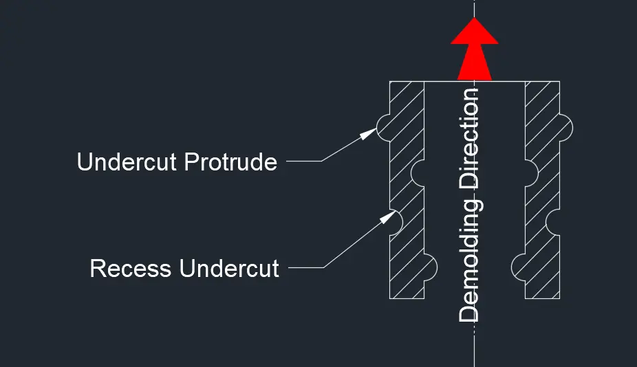
As the plastic cools, it shrinks around the insert, creating a robust mechanical lock. Since most thermoplastics form no natural chemical bond with metal, inserts must incorporate knurls, grooves, or undercuts to resist pull-out and rotation forces.
Step 5: Part Ejection.
Once the plastic reaches sufficient rigidity, the mold opens and the finished composite part is ejected.ready for use without further assembly.
Critical Wall Thickness Guidelines.
One of the most common and costly mistakes in insert molding design is treating the metal insert as an afterthought. Engineers often design the plastic part first, then try to fit the insert into whatever space remains. The correct approach is the opposite: design the metal insert first, then design the plastic around it.This distinction matters because the insert’s shape directly controls the surrounding wall thickness requirements. Irregular insert geometries: rectangular, hexagonal, square, or any profile with sharp corners create localized stress concentrations that demand careful wall thickness management to prevent cracking.
The thermoplastic surrounding an insert must simultaneously satisfy several competing demands:
- Flow easily during injection to fill and pack the cavity at optimal pressure.
- Shrink predictably during cooling to form a tight mechanical lock around the insert.
- Stretch without cracking as it contracts around the insert geometry.
Suggested Minimum Wall Thicknesses for Inserts of Various Diameters
| Plastic Material | Diameter 0.125 in (3.17 mm) | Diameter 0.250 in (6.35 mm) | Diameter 0.375 in (9.52 mm) | Diameter 0.500 in (12.7 mm) | Diameter 0.750 in (19.0 mm) | Diameter 1.00 in (25.4 mm) |
|---|---|---|---|---|---|---|
| ABS | 0.125 (3.17) | 0.250 (6.35) | 0.375 (9.52) | 0.500 (12.7) | 0.750 (19.0) | 1.00 (25.4) |
| Acetal | 0.062 (1.57) | 0.125 (3.17) | 0.187 (4.75) | 0.250 (6.35) | 0.375 (9.52) | 0.500 (12.7) |
| Acrylics | 0.093 (2.36) | 0.125 (3.17) | 0.187 (4.75) | 0.250 (6.35) | 0.375 (9.52) | 0.500 (12.7) |
| Cellulosics | 0.125 (3.17) | 0.250 (6.35) | 0.375 (9.52) | 0.500 (12.7) | 0.750 (19.0) | 1.00 (25.4) |
| Ethylene vinyl acetate | 0.040 (1.02) | 0.085 (2.16) | Not recommended | Not recommended | Not recommended | Not recommended |
| FEP (fluorocarbon) | 0.025 (0.64) | 0.060 (1.52) | Not recommended | Not recommended | Not recommended | Not recommended |
| Nylon | 0.125 (3.17) | 0.250 (6.35) | 0.375 (9.52) | 0.500 (12.7) | 0.750 (19.0) | 1.00 (25.4) |
| Noryl (modified PPO) | 0.062 (1.57) | 0.125 (3.17) | 0.187 (4.75) | 0.250 (6.35) | 0.375 (9.52) | 0.500 (12.7) |
| Polyallomers | 0.125 (3.17) | 0.250 (6.35) | 0.375 (9.52) | 0.500 (12.7) | 0.750 (19.0) | 1.00 (25.4) |
| Polycarbonate | 0.062 (1.57) | 0.125 (3.17) | 0.187 (4.75) | 0.250 (6.35) | 0.375 (9.52) | 0.500 (12.7) |
| Polyethylene (HD) | 0.125 (3.17) | 0.250 (6.35) | 0.375 (9.52) | 0.500 (12.7) | 0.750 (19.0) | 1.00 (25.4) |
| Polypropylene | 0.125 (3.17) | 0.250 (6.35) | 0.375 (9.52) | 0.500 (12.7) | 0.750 (19.0) | 1.00 (25.4) |
| Polystyrene | Not recommended | Not recommended | Not recommended | Not recommended | Not recommended | Not recommended |
| Polysulfone | Not recommended | Not recommended | Not recommended | Not recommended | Not recommended | Not recommended |
| Surlyn (ionomer) | 0.062 (1.57) | 0.093 (2.36) | 0.125 (3.17) | 0.187 (4.75) | 0.250 (6.35) | 0.312 (7.92) |
| Phenolic GP | 0.093 (2.36) | 0.156 (3.96) | 0.187 (4.75) | 0.218 (5.53) | 0.312 (7.92) | 0.343 (8.71) |
| Phenolic (medium-impact) | 0.078 (1.98) | 0.140 (3.56) | 0.156 (3.96) | 0.203 (5.16) | 0.281 (7.14) | 0.312 (7.92) |
| Phenolic (high-impact) | 0.062 (1.57) | 0.125 (3.17) | 0.140 (3.56) | 0.187 (4.75) | 0.250 (6.35) | 0.281 (7.13) |
| Urea | 0.093 (2.36) | 0.156 (3.96) | 0.187 (4.75) | 0.218 (5.53) | 0.312 (7.92) | 0.343 (8.71) |
| Melamine | 0.125 (3.17) | 0.187 (4.75) | 0.218 (5.53) | 0.312 (7.92) | 0.343 (8.71) | 0.375 (9.52) |
| Epoxy | 0.020 (0.51) | 0.030 (0.76) | 0.040 (1.02) | 0.050 (1.27) | 0.060 (1.52) | 0.070 (1.78) |
| Alkyd | 0.125 (3.17) | 0.187 (4.75) | 0.187 (4.75) | 0.312 (7.92) | 0.343 (8.71) | 0.375 (9.52) |
| Diallyl phthalate | 0.125 (3.17) | 0.187 (4.75) | 0.250 (6.35) | 0.312 (7.92) | 0.343 (8.71) | 0.375 (9.52) |
| Polyester (premix) | 0.093 (2.36) | 0.125 (3.17) | 0.140 (3.56) | 0.187 (4.75) | 0.250 (6.35) | 0.281 (7.14) |
| Polyester TP | 0.062 (1.57) | 0.125 (3.17) | 0.187 (4.75) | 0.250 (6.35) | 0.375 (9.52) | 0.375 (9.52) |
Optimizing Component Anchorage.
Here is a fact that surprises many engineers new to insert molding: thermoplastics form no natural chemical bond with metal. None. The entire holding strength of an insert-molded part depends on mechanical anchorage , the physical geometry you machine into the insert before it ever enters the mold.
Get this right, and your part holds for decades. Get it wrong, and the insert spins, pulls out, or cracks the surrounding plastic within the first few thousand cycles.
Resisting Torque and Pull Out: The Two Forces That Destroy Inserts:
Every insert faces two destructive forces in service: torque (rotational) and tension (axial pull-out). Your anchorage design must address both independently.
For torque resistance, coarse diamond knurling on round metal stock is the industry standard. The knurl pattern bites into the surrounding plastic as it shrinks during cooling, creating a mechanical grip that resists rotation effectively. It also distributes stress evenly around the insert circumference, reducing the risk of cracking.
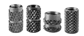
For pull-out resistance, circumferential grooves machined into the insert body are the primary solution. As the plastic shrinks around the insert, it flows into these grooves and locks the insert axially.
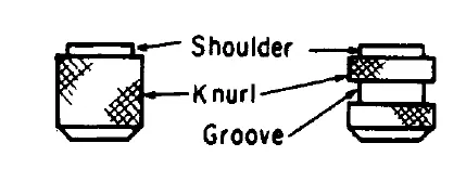
One important detail on groove design: a single wide groove in the center of the insert outperforms multiple narrow grooves. The wide center groove allows the plastic to creep inward symmetrically during shrinkage, reducing internal strain. Multiple narrow grooves create multiple stress concentration points and increase the risk of cracking between them.
Engineering for Thermal Expansion Mismatch.
Metal and plastic do not expand and contract at the same rate. Not even close. Steel has a coefficient of linear thermal expansion (CLTE) of approximately 1.1×10⁻⁵/°C. An unfilled polyethylene can be ten times higher. Every time the temperature changes, the plastic is trying to move significantly more than the metal insert it is locked around and it has nowhere to go.This is the fundamental engineering challenge of insert molding. The plastic is not free to expand and contract. The metal insert constrains it. And that constraint generates internal stress.Thermal expansion mismatch does not always fail immediately. Sometimes it fails three years into service, in the field, at the worst possible moment.
Design Solutions That Actually Work:
- Build in the ability to float. Instead of rigidly constraining the plastic to the metal, incorporate slots or clearance holes that allow relative movement along one or more axes. This is standard practice in automotive and electronics insert molding where wide temperature swings are expected.
- Add reinforcement to reduce CLTE. Glass fiber, mica, and carbon fiber reinforcements lower the thermal expansion coefficient of the base polymer significantly, making it more compatible with metal. A 30% glass-filled nylon, for example, behaves very differently from unfilled nylon when bonded to a steel insert.
- Use elastomeric interfaces. A thin elastomeric gasket or coating at the metal-plastic interface acts as a buffer, absorbing differential movement rather than forcing the stress into the plastic itself.
- Maintain adequate wall thickness. The geometry around the insert matters. Sharp internal corners on the insert concentrate stress. Insufficient wall thickness leaves the plastic with no capacity to absorb shrinkage forces. Maintaining a wall thickness of 1.75 to 2 times the insert diameter gives the plastic enough material to flex and absorb stress without cracking.
Process Techniques That Reduce Thermal Stress.
- Preheat the inserts. Heating metal inserts to 250–300°F (121–149°C) before placing them in the mold reduces the temperature shock when molten plastic contacts cold metal. The plastic solidifies more uniformly, locking in less residual stress. This is one of the simplest and most effective things you can do to improve insert-molded part quality.
- Anneal the finished parts. A controlled post-molding heating cycle allows the polymer molecules to rearrange and relieve locked-in stresses before the part enters service. For precision applications or those involving wide temperature ranges, annealing is not optional — it is part of the process.
- The underlying principle across all of these solutions is the same: you cannot eliminate the CLTE mismatch between plastic and metal, but you can design and process around it so that the stress has somewhere to go other than into a crack.
Precision Tolerancing and Tool Design.
Insert molding leaves very little room for dimensional error. The metal insert must fit the mold cavity precisely,tight enough to prevent flash, but not so tight that it damages the tool on closing. Getting this balance right starts with the insert itself.
Insert Dimensional Tolerances:
For machined metal threaded inserts, the tolerance requirements are tighter than most engineers expect:
- Minor diameter: precision grade tolerance of ±0.0005 in
- Overall length: precision grade tolerance of ±0.001 in
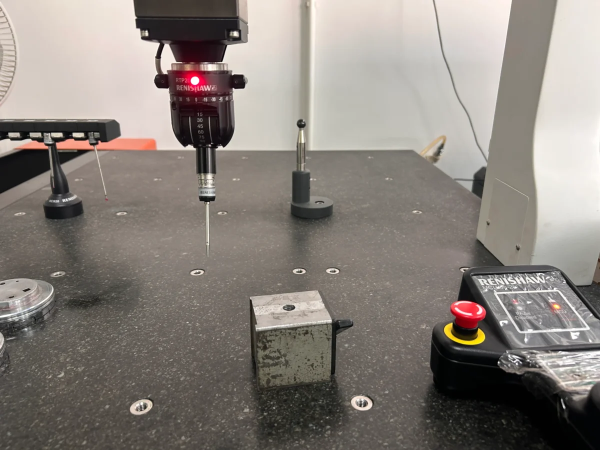
Length tolerance is critical for through-inserts: Too short, plastic flashes at the parting line. Too long, the mold steel gets crushed. Either way, it’s costly.Dimensional inconsistency across a batch is a leading cause of insert molding defects. Before production, sample check dimensions across the entire batch ,not just the first piece.
Mold Design for Insert Stability.
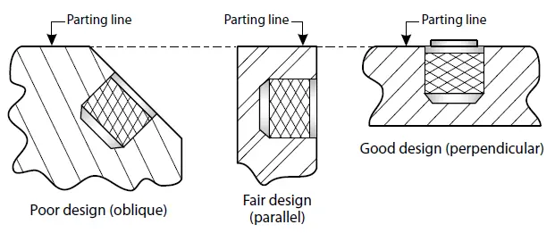
Parting line orientation. Wherever possible, orient inserts perpendicular to the mold parting line. This simplifies location, improves sealing, and reduces wear on the mold surfaces that contact the insert. Angled inserts create uneven contact forces and accelerate tool wear at the contact points.
Venting around inserts.
Deep ribs and boss walls surrounding inserts are natural air traps. As plastic fills the cavity, displaced air must escape or it compresses, heats up, and burns the plastic. Vent slots at the insert periphery, or controlled clearance between the insert and the mold steel, are standard practice for preventing gas porosity and burn marks in insert-molded parts.
Equipment Selection.
Vertical injection molding machines are the preferred platform for insert molding. The horizontal parting line keeps the lower mold half facing upward, allowing gravity to seat and hold inserts in position during mold closing. On a horizontal machine, inserts must be retained by pins or fixtures alone,gravity works against you.
For high-volume production, rotary or shuttle table configurations significantly reduce cycle time. While one station is under injection, the operator or robot loads inserts into the second station. The two stations alternate, eliminating the loading time that would otherwise extend every cycle.
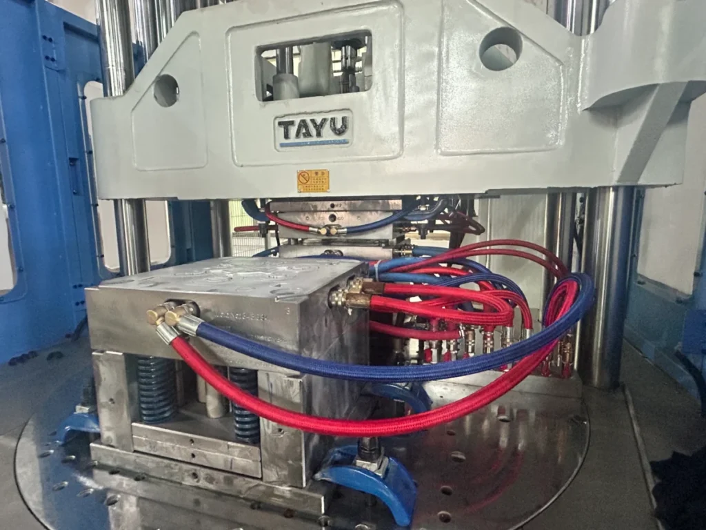
Retaining and location features. During injection, molten plastic enters the cavity at high pressure. Without positive location, the insert moves . This is a failure mode known as core shift. Standard solutions include:
- Retaining pins that hold the insert in position through the injection and packing phases
- Support pillars for large-area inserts that would otherwise deflect under injection pressure
- Delay ejection retainer pins for oversized inserts, which remain engaged until packing is complete before retracting.
How To Choose An Insert Molding Manufacturer?
Most suppliers will tell you they can do insert molding. Fewer actually understand it. Here is how to tell the difference before you commit tooling budget to the wrong partner.
Check Their Equipment First.
Ask one simple question: do you run vertical molding machines?
Vertical presses are the standard for insert molding. The horizontal parting line uses gravity to seat inserts in the lower mold half during closure. a practical advantage that horizontal machines simply cannot replicate without additional fixturing. If a supplier runs only horizontal machines for insert molding work, that is your first warning sign.
For high-volume production, look for rotary or shuttle table configurations. These allow insert loading on one station while the other is under injection.cutting cycle time and reducing barrel residence time for heat-sensitive resins.
Ask About Their Pre-Processing Protocol.
Evaluate Their DFM Capability.
A competent insert molding supplier does not just run your parts.they review your design before cutting steel.
Specifically, they should be checking:
- Wall thickness ratio: plastic surrounding the insert should be 1.75 to 2 times the insert’s outer diameter to absorb shrinkage stresses without cracking
- Corner geometry: sharp internal corners on inserts are stress concentration points — a good supplier will flag these and recommend chamfers or radii
- Anchorage features: knurl pattern, groove placement, and undercut geometry should be verified against the specific resin and application requirements
Other quality indicators worth asking about:
Low-pressure mold protection: machines should be equipped with sensitive pressure monitoring that stops the clamp immediately if an insert is misaligned. preventing a misplaced insert from crushing tool steel worth tens of thousands of dollars.
SPI mold classification: confirm the mold is built to the appropriate class for your expected production volume , a Class 101 tool for high-volume precision work, a Class 103 for moderate volumes
Conclusion:
Insert molding is not a process you can approach casually. The difference between a part that performs for a decade and one that fails in the field often comes down to decisions made before the mold is ever cut.insert geometry, wall thickness ratios, resin selection, and anchorage design.
The principles covered in this guide,from the 1.75x wall thickness rule to preheating inserts at 250–300°F are not theoretical guidelines. They come from decades of production experience.
If you are designing an insert molded component or evaluating suppliers for your next project, Qlution Mold offers free DFM analysis for every new project. Contact us today to discuss your requirements.