Ball and socket snap fits are essential for products that need multi-directional movement, such as phone mounts, medical joints, and toys. However, designing a reliable snap fit is challenging. If the tolerances are too tight, the part may break; if they are too loose, the joint will wobble.In this guide, we will break down the key design parameters, material selection, and geometry secrets to help you create perfect ball and socket snaps for injection molding.
What Are Ball and Socket Snaps? Definition, Mechanism, and Joint Classification.
In plastic snap fit design, ball and socket snaps also called spherical snap-fits are one of four main snap fit types, alongside cantilever, annular, and torsional. Like the others, they rely on elastic recovery to hold parts together. The difference lies in geometry: the spherical form resists loads from multiple directions and, in many applications, keeps articulating after assembly.
A ball and socket snap is a constrained sphere version of the annular snap-fit. A standard annular snap like bottle caps or lens retainers works along a single axis. The spherical variant extends that locking principle across a full 360° envelope, making it the go-to choice for joints that need to rotate or pivot in service.
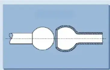
The joint consists of two features:
Ball (male):
A dome-shaped or fully spherical protrusion molded onto one component.
Socket (female):
A compliant, partial sphere receptacle on the mating part, typically segmented into “snap logs” to enable elastic deflection during assembly.
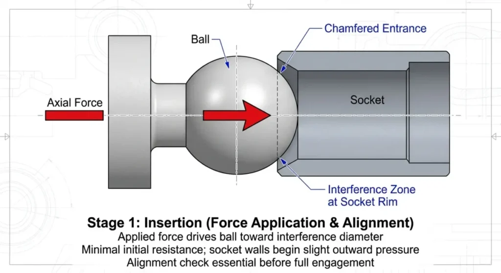
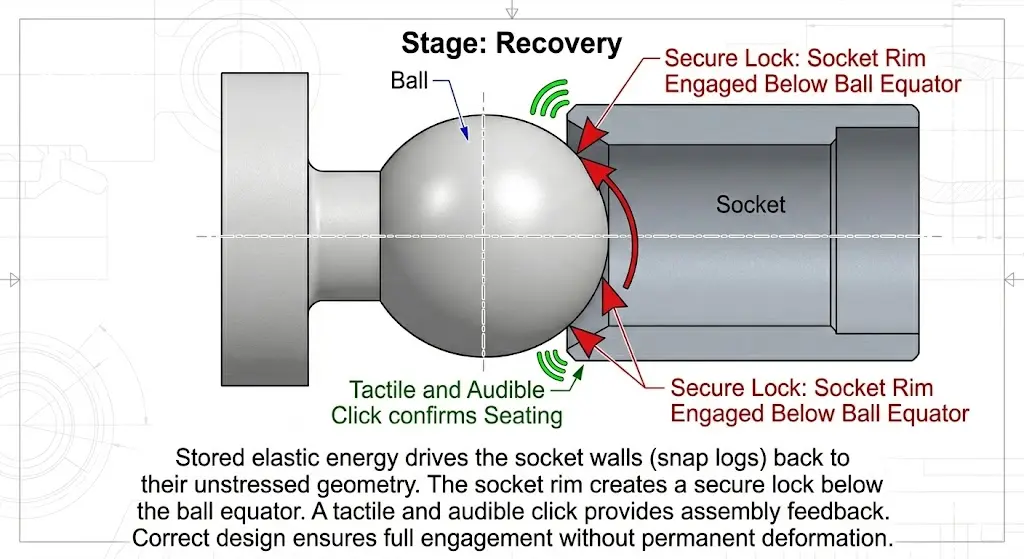
Mechanism: Three Stage Snap Engagement:
Stage Insertion: The ball contacts the chamfered entrance of the socket. Axial force is applied, directing the ball toward the interference zone at the socket rim.
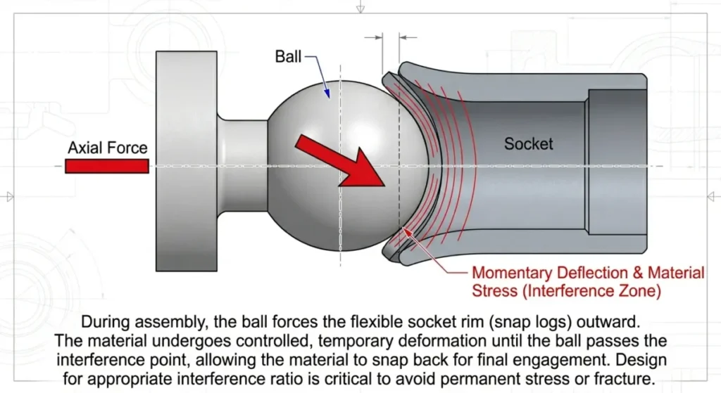
Stage Deflection: The socket walls deflect outward radially as the ball’s equator passes through the interference zone. This is the highest-stress moment in the assembly cycle. Peak strain occurs at the base of the snap logs. the fixed end of each socket segment making this the most fracture-prone location in rigid material applications.
Stage Recovery: Once the ball clears the rim, stored elastic energy drives the socket walls back to their unstressed geometry. The socket rim engages below the ball equator, completing the lock. A tactile and audible click confirms seating.
Where Ball and Socket Snaps Are Used:
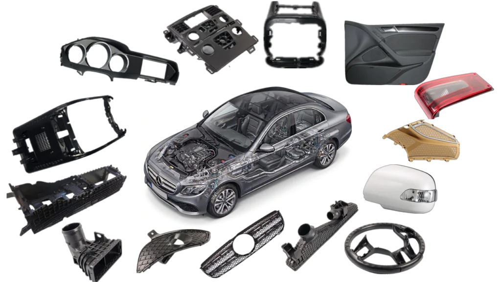
Automotive:
The automotive sector represents the highest engineering demand environment for spherical snap-fits, with applications spanning both structural mechanical joints and cosmetic interior assemblies.
Mechanical Linkages:The application is the connecting rod end ball joint a snap-fit securing ring in unreinforced Nylon 6/6 paired with an acetal ball. This material pairing is deliberate: nylon provides the elastic compliance needed for snap engagement, while acetal’s inherently low coefficient of friction minimizes wear at the articulating interface. The result is a self-lubricating, metal-free pivot joint that survives tens of millions of cycles.
Sensor Integration:Gasoline tank level sensors and automotive speed sensors use spherical snaps to create pivot attachments that must tolerate continuous vibration, wide temperature swings (−40°C to +120°C under hood), and fluid exposure conditions that would degrade adhesive or press-fit alternatives within months.
Interior Trim Reflector attachments on inner door panels are a volume application: the snap must resist road vibration without rattling, yet remain manually separable for service access. This is a classic separable spherical snap use case, where the return angle is tuned to require deliberate pull off force without tooling.
Industrial Equipment:
the engineering case for plastic ball and socket snaps is fundamentally economic as well as functional. Replacing a machined metal bearing assembly with a molded spherical snap eliminates the bearing housing, retaining ring, and assembly labor. reducing total installed cost often by 40–60%.
Journal Bearings and Shaft Supports
Split bushing journal bearings for manually operated shafts :window actuators, wheel suspension linkages use spherical snaps to allow angular misalignment while maintaining positive retention. The split bushing geometry is itself a DFM-driven decision: it enables straight-pull molding without side actions while providing the flexibility needed for snap engagement.
Movable Joint Mechanisms
Access doors, pivoting tool handles, and adjustable equipment mounts use ball and socket snaps classified as Movable/Restricted Motion joints. The socket geometry is designed to allow controlled angular rotation within a defined cone angle while preventing axial pull-out a constraint that requires careful retention angle selection (typically 70°–85°).
Transmission and Gear Assemblies
In gear assemblies and differential power gearing, spherical snap joints transmit angular motion through flexible linkages where shaft misalignment is expected. Here, material selection shifts toward POM (acetal) or PA66 GF for dimensional stability and fatigue resistance under cyclic torsional loading.
Consumer electronics
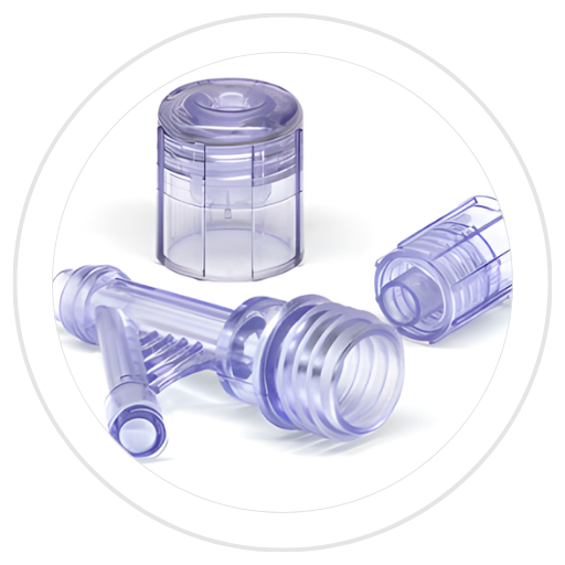
Consumer electronics OEMs leverage spherical snaps to eliminate exposed hardware and support Design for Disassembly mandates, with applications ranging from printer chassis and power tool housings to miniaturized phone and game console mounts where interference tolerances tighten to ±0.03 mm which is a mold precision challenge as much as a design one. In medical and pharmaceutical environments, the same joint geometry addresses an entirely different constraint set: biocompatibility, sterilizability, and zero loose hardware tolerance, making spherical snaps the preferred solution for diagnostic instrumentation joining dissimilar materials and for fluid delivery connectors requiring thousands of single-handed disconnect cycles at deliberately low retention forces (5–15 N). At the opposite end of the volume and cost spectrum, the toy and recreational goods industry applies the same elastic recovery principle to action figure limb joints designed to withstand 50–80 N child-applied pull loads and to safety critical release mechanisms in ski bindings and helmet systems, where retention force is not maximized but reverse-engineered from a defined threshold release requirement.
Joint Geometry Fundamentals: Material, Ball Diameter, Engagement Angle, and Socket Depth.
The core requirement: ductility:
- Ductile materials tolerate wider interference and are forgiving of dimensional variation between production lots
- Rigid materials (especially glass-filled grades) produce dangerously high assembly forces and fracture at the snap log root without warning
- Default to ductile materials. Only use rigid engineering grades when temperature, chemical, or structural requirements demand it.and compensate with 4 split snap log geometry.
- Is the joint movable (rotating after assembly)? → POM ball + PA66 socket
- Is the joint fixed, single-assembly, low cost priority? → PP Copolymer or PE
- Is the joint fixed, repeated assembly (> 100 cycles)? → PA66 or POM, apply 60% strain reduction
- Is a rigid material unavoidable (thermal, chemical, structural)? → Mandatory 4-split snap log geometry, verify strain at ±temperature extremes
- Is glass fiber reinforcement required? → Consider collapsible core mold design; snap log forced ejection will likely fracture the part
Material Performance Comparison
| Material | Type | Max Permissible Strain | Fatigue Resistance | Friction / Wear | Key Limitation |
|---|---|---|---|---|---|
| Acetal (POM) Homopolymer | Semi-crystalline | 5% | Excellent | Very low (self-lubricating) | Higher cost vs. PP |
| Nylon 6/6 Unreinforced | Semi-crystalline | 6–10% | Excellent | Low (self-lubricating) | Moisture absorption affects dimensions |
| PP Copolymer | Semi-crystalline | 6–8% | Good | Moderate | Lower stiffness; creep under load |
| PE (HDPE) | Semi-crystalline | 6–8% | Good | Low | Low stiffness; limited temp range |
| Polycarbonate (PC) | Amorphous | 4% | Moderate | Moderate | Notch sensitive; stress crack risk |
| ABS | Amorphous | 2% | Low | Moderate | Low strain limit; brittle at root |
| Glass-Filled Nylon (PA66 GF30) | Semi-crystalline + filler | 1–2% | Poor | Higher (abrasive) | Snap log fracture risk; slotting mandatory |
| Glass-Filled PC/ABS | Amorphous + filler | 1–2% | Poor | Higher | Not recommended without collapsible core |
Ball Diameter (d):
Key design rules:
- The surrounding socket wall thickness should be 1.75× to 2× the ball diameter to handle assembly stresses and shrinkage induced hoop stress without cracking
- Permissible socket depth (undercut) is expressed as a percentage of d, and that percentage is material-dependent.
| Material | Max Undercut as % of d | Notes |
| Nylon 6/6 (unreinforced) | 6% – 10% | High ductility; most forgiving material for snap-fits. |
| Acetal (POM) | < 5% | Lower elongation; requires careful stripping from the mold. |
| PP Copolymer | 5% – 8% | Good flexibility; excellent low-cost option for light duty. |
| ABS | 2% – 3% | Brittle; conservative interference/undercut required. |
| Glass-filled grades | < 2% | Very stiff; a slotted socket (snap logs) is mandatory. |
Engagement Angle:
- Recommended baseline: 30°: explicitly specified in engineering handbooks for spherical snap-fits; provides a reliable balance between smooth assembly and adequate retention geometry
- Acceptable range: 25°–35° : workable for most material and geometry combinations
- Hard limit: 45° :angles above 45° generate assembly forces that exceed ergonomic limits for hand assembly and risk snap log fracture in rigid materials; avoid in all standard designs
DFM for the Ball And Socket Snap Feature: Draft Angles, Surface Finish, And Undercut Solutions:
Minimum draft: 0.5° per side the absolute floor; anything less risks scuffing on textured or high-gloss surfaces Standard recommendation: 1°–3° per side for most thermoplastics under normal conditions.
Surface Finish:
| SPI Grade | Finish Type | Typical Application |
|---|---|---|
| A-1 / A-2 | Mirror diamond polish | Rigid, brittle polymers (PC, ABS) — minimizes ejection friction |
| B-2 / B-3 | Fine stone finish | General-purpose thermoplastics; good balance of release and texture |
| D-2 | Vapor-honed / light blast | Soft elastomers (TPE, TPU) — prevents vacuum stiction |
| D-3 | Coarse dry blast | Draft-insensitive surfaces; non-cosmetic internal features |
All final polishing on mold cores and cavities must be performed in the line of draw: the direction the part travels during ejection. Polishing perpendicular to the draw direction creates microscopic surface undercuts that dramatically increase ejection force and cause surface streaking. This is one of the most common, and most avoidable, DFM errors in snap-fit tooling.
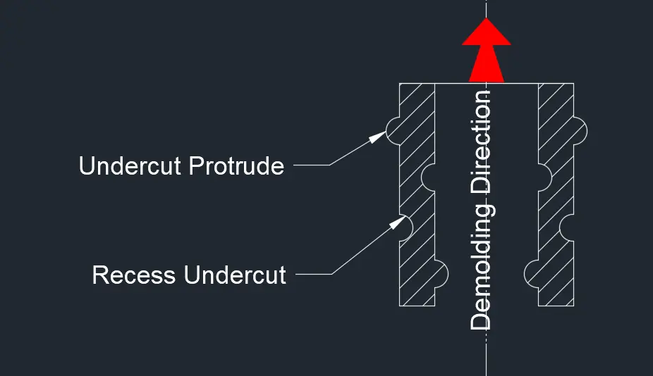
Undercut Solutions:
Forced Ejection (Stripping).
The simplest and most cost-effective approach. The part is pushed off the mold core while the material is still warm enough to deflect elastically over the undercut, then recover.
Viable when:
- Undercut depth is < 5% of diameter for Acetal (POM)
- Undercut depth is 6%–10% of diameter for unreinforced Nylon 6/6
- Lead-in and return angles are between 30° and 45° shallow enough for the plastic to slide over the mold geometry without tearing.
Shut-off Design (Preferred DFM Approach)
The undercut is eliminated entirely by incorporating a slot or window at the base of the snap feature that allows the mold to form the geometry using simple open-and-close action with no moving parts. No side actions, no lifters, no additional maintenance points.
Mechanical Actions:
When the material is too rigid to strip and the geometry cannot accommodate a shut-off, mechanical tool components are required:
Lifters:used for internal undercuts inside the socket cavity; retract inward as the mold opens
Sliders / side-action cams ,this solution used for external features on the ball component.retract laterally before ejection.Mechanical actions increase tooling cost, extend lead time, and introduce additional maintenance requirements They also add cycle time. Use them when the design genuinely requires it, not as the default solution when a shut-off or stripping approach has not been seriously evaluated.
Conclusion:
Ready to Move From Design to Production?
At Qlution Mold, we work with product engineers and procurement teams at every stage of the snap-fit development process from early DFM review through tool design, steel qualification, and first-article validation.
What that means in practice:
- DFM review before tooling starts: we identify interference tolerance issues, draft deficiencies, and undercut strategy conflicts at the drawing stage, not after steel is cut
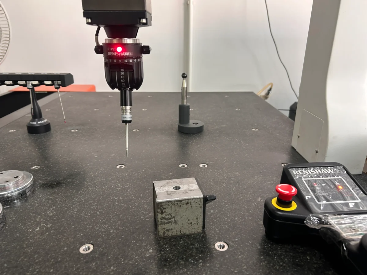
- Tight dimensional control on snap features: ball diameter tolerances held to ±0.05 mm, socket depth verified against first-article pull-force testing
- Mold concept matched to your material :whether your design calls for forced ejection in PP, a shut-off in PA66, or a lifter system in glass-filled PC, we specify the tooling approach before quoting, not after problems appear in sampling
If you are at the design stage and want a DFM review before committing to tooling, or if you have an existing snap fit design that is producing inconsistent assembly force or premature fatigue failures, we are the right conversation to have.
Contact Qlution Mold for a no-commitment DFM review.