Injection molding defects are rarely random. Every sink mark, weld line, and short shot has a root cause and in most cases, that cause can be traced back to one of three places: part design, mold design, or process parameters.The challenge is knowing which one.
This guide covers the most common injection molding defects encountered in production, what causes them, and how to eliminate them systematically whether you are troubleshooting an existing tool or trying to prevent problems before the first shot is pulled.
Understanding the Root Causes: Machine, Mold, and Material.
Consistent injection molding is never a matter of luck,it is a delicate symphony between four critical sections: The Machine, The Mold, The Material, and The Operator. As illustrated in our Fishbone Diagram, these elements are so deeply interconnected that one “out-of-tune” variable can ruin the entire performance.

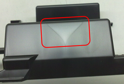
1.Sink Mark:
The Definition of Sink Marks:
A sink mark is a localized surface depression or indentation on a molded part, primarily caused by thermal contraction (internal shrinkage) during the cooling phase. The phenomenon occurs because the part’s outer skin solidifies first against the cool mold walls, while the thicker internal core remains molten. As this internal core eventually cools and shrinks, it generates negative pressure that pulls the still-pliable surface inward, creating a visible dip or “sink” on the exterior of the part.
To optimize product design for the prevention of sink marks, engineers must prioritize Wall Thickness design by adhering to the uniformity Rule, as nonuniform sections create differential cooling rates where thick areas retain heat longer and pull the surface inward due to excessive shrinkage potential. This is further complicated by rib and boss geometry, where maintaining a rib-to-wall thickness ratio of 40% to 60% and employing boss Isolation techniques are critical to minimizing mass accumulation at junctions that typically demonstrate as sinks on the opposite “show surface.” Furthermore, Fillet and Radius Optimization is essential, as excessive radii can create “hot spots” by increasing local section thickness. A proper gating position must also be selected, ensuring a thick to thin flow. If the melt freezes in a thin section before reaching a thicker area, it creates a mechanical blockage that prevents holding pressure from compensating for shrinkage. Finally, consideration of material morphology is vital, as semi-crystalline resins like PP or PE possess significantly higher shrinkage rates than amorphous resins like PC or ABS, making them very sensitive to these design related variables.
From a manufacturing perspective, once the part design is finalized, sink marks primarily stem from a failure to inject and maintain sufficient material volume to offset natural volumetric contraction. To solve this, packing and holding pressure must be optimized, insufficient packing pressure or premature release of pressure before the gate solidifies allows molten plastic to flow back, resulting in uncompensated shrinkage. Thermal management is equally critical, as excessive melt or mold temperatures intensify thermal contraction, while inefficient cooling designs create localized “hot spots” that delay solidification. Furthermore, Machine Performance must be verified to ensure the non-return valve is not leaking and that a sufficient material cushion is maintained to transmit pressure effectively. Finally, we should pay attention to unbalanced flow patterns in multi-cavity molds and inadequate venting, both of which obstruct the consistent, dense packing of material against the cavity walls.
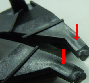
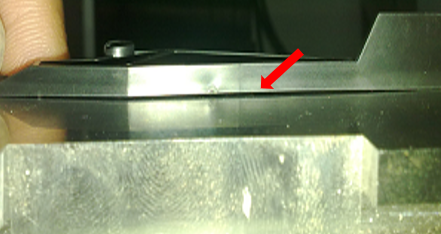
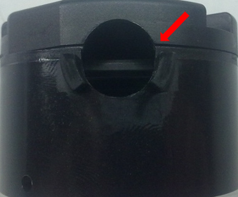
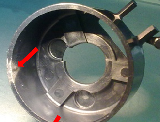
2.Flash (Burrs):
The Definition Of Flash (Burrs):
Flash, also known as burrs, is a common defect where excess plastic is forced out of the mold cavity, typically at the parting line or along ejector pins. This results in unwanted thin layers of plastic attached to the finished part, requiring costly manual trimming.
Tips To Injection Molded Part Designer:
· Avoid Feather Edges: Parts designed with extremely thin, tapered edges require fragile steel sections in the mold. These “feather” areas are prone to chipping, creating gaps where plastic can escape.
- Solution: Maintain a minimum wall thickness at the edges to ensure mold steel strength.
· Manage Wall Thickness: Abrupt changes in thickness lead to uneven cooling and flow. If a thick section is located at the end of the flow path, it may require excessive pressure to fill, which can blow the mold open.
- Solution: Design for uniform wall thickness to ensure balanced pressure distribution.
· Optimize Parting Lines: Poorly placed parting lines can lead to mold deflection under high internal gas pressure.
- Solution: Position the parting line to balance heat removal and handle clamping forces effectively.
Tips To Mold And Tooling Guy:
If the mold itself cannot maintain a perfect seal, flash is inevitable regardless of the machine settings.
- Parting Line Integrity: Nicks, cracks, or even tiny pieces of trapped plastic on the mold faces prevent the two halves from closing tightly.
- Solution: Implement a strict mold cleaning schedule and inspect for surface damage regularly.
- Mold Plate Deflection: If there are not enough support pillars behind the mold plates, the steel can bend slightly under high injection pressure.
- Solution: Add more support pillars to the mold base to increase structural rigidity.
- Venting Specifications: Vents are necessary to let air out, but if they are too deep (typically exceeding 0.025 mm for most plastics), the molten resin will follow the air out.
- Solution: Precisely grind vents to the material-specific depth and replace worn venting components.
Tips To Injection Molding Guy:
Process related flash occurs when the internal pressure of the plastic exceeds the machine’s ability to keep the mold halves sealed.
- Clamping Force (Tonnage): If the machine’s clamping force is too low for the part’s projected area, the injection pressure will overcome the clamp and push the mold halves apart.
- Solution: Increase the clamp tonnage or move the mold to a larger tonnage machine.
- Injection and Packing Pressure: A sudden spike in pressure,especially during the transition from injection to packing (V/P transfer),this is a frequent cause of flash.
- Solution: Slow down the injection speed and optimize the V/P transfer point to prevent pressure spikes.
- Melt Temperature and Viscosity: Higher temperatures make the plastic “thinner” (lower viscosity), allowing it to seep into microscopic gaps and vents more easily.
- Solution: Reduce the melt or mold temperature to increase the material’s resistance to flow into gaps.
- Material Preparation: Excess moisture in the resin can degrade the polymer, resulting in a watery melt that flashes easily.
- Solution: Ensure the resin is properly dried according to the manufacturer’s specifications before production.
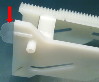
3.Short Shots:
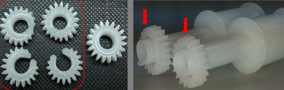
The Definition Of Short Shots:
Short Shot occurs when the polymer melt fails to completely fill the mold cavity, typically appearing as rounded or missing edges in thin sections or at the end of a flow path. This defect is a result of excessive flow resistance or insufficient material volume.
Tips To Injection Molded Part Designer:
Short shots are often rooted in geometric constraints that exceed the physical flow limits of the resin.
- Wall Thickness & L/t Ratio: Walls that are too thin create high flow resistance, causing the melt to “freeze off” before reaching the end. If the flow length to thickness (L/t) ratio is too low for the specific resin, the cavity will not fill.
- Flow Hesitation: Significant variations in thickness cause the melt to take the path of least resistance (thick areas), while slowing down or hesitating in thin areas, leading to premature solidification.
- Solutions: Use Mold Flow Analysis to predict filling patterns. Increase thickness in critical sections to act as “flow leaders” and simplify complex, narrow ribs to reduce overall resistance.
Tips To Mold And Tooling Guy:
Mechanical obstructions or thermal imbalances within the tool can physically block the path of the melt.
- Venting and Back-Pressure: Inadequate venting traps air or gas, creating a high-pressure barrier that the melt cannot overcome.
- Feed System Restrictions: Small gates, narrow runners, or a cold nozzle orifice cause significant pressure drops. In multi-cavity tools, unbalanced runner layouts lead to inconsistent filling across cavities.
- Solutions: Clean or add vents to the last-to-fill areas
- Enlarge gates and runners to reduce pressure loss and ensure all hot runner tips are free of contamination or carbon buildup.
Tips To Injection Molding Guy:
Process related short shots occur when the machine fails to deliver or maintain enough pressure and volume.
- Pressure and Shot Size: If the shot volume (dosage) is too small or the injection pressure is insufficient to overcome the mold resistance, the part will remain incomplete.
- Melt Viscosity: Low barrel temperatures increase viscosity, making the plastic too “thick” to flow into narrow gaps.
- Machine Integrity: A worn check valve (non-return valve) allows material to leak back during injection, while a missing “cushion” (when the screw bottoms out) prevents the transmission of holding pressure.
- Solutions: Increase injection pressure, speed, or melt temperature. Maintain a stable cushion of 3mm to 6mm to ensure effective packing and replace worn screw tips or check valves to prevent backflow.
4.Warpage:
The Definition Of Warpage:
Warpage is a structural distortion where the molded part deviates from its intended CAD geometry. It is fundamentally driven by differential shrinkage—variations in the rate or degree of contraction across different regions or orientations of the part.Achieving dimensional stability requires a holistic approach across design, tooling, and processing.
Tips To Injection Molded Part Designer:
The Uniformity Mandate: The primary rule of plastic design is maintaining symmetrical wall sections. Non-uniform walls create internal moments; thicker sections retain heat longer and shrink more than adjacent thin walls, physically pulling the part out of shape.
Proportional Feature Design: Protrusions such as ribs and bosses must follow the 40–60% thickness rule relative to the nominal wall. This prevents localized mass accumulation that leads to internal stress and buckling.
Increasing Geometric Rigidity: Large, flat surfaces are naturally susceptible to “potato-chipping.” Engineers should incorporate curves, corrugations, or reinforced ribs to increase the moment of inertia, providing the structural stiffness necessary to resist post-molding distortion.
Tips To Mold And Tooling Guy:
Differential Cooling (Core vs. Cavity): Inconsistent cooling between the mold halves is a leading cause of bowing. If the core is hotter than the cavity, the part will shrink more on that side, causing it to bow toward the warmer surface.
Proper Gating: Gating at the center of a flat geometry promotes radial flow, which often leads to bowl-shaped warpage. Strategic gating at the thickest sections or utilizing multiple gates—is essential to balance the pressure distribution across the cavity.
Balanced Feed Systems: Naturally balanced runners ensure that every cavity in a multi-cavity tool experiences identical pressure and temperature profiles, preventing cavity-to-cavity dimensional variations.
Tips To Injection Molding Guy:
Molecular Orientation: High injection pressures and rapid fill rates can induce high molecular orientation, leading to anisotropic shrinkage (shrinking differently along the flow vs. across the flow). Elevating melt and mold temperatures allows molecules to “relax” before solidification, reducing molded-in stress.
Pressure Gradients: While packing pressure compensates for volumetric contraction, overpacking the gate area while the extremities remain under-packed creates a pressure gradient. This imbalance is a frequent trigger for saddle-shaped warpages.
Thermal Ejection Limits: Parts must not be ejected until they have cooled below their Heat Deflection Temperature (HDT). Premature ejection leaves the part too pliable, causing it to distort under the mechanical force of the ejector pins.
5.Burn Marks:
The Definition Of Burn Marks:
Burn Marks, often referred to as “Dieseling” or Gas Traps, are small, carbonized black spots or streaks that typically manifest at the end of a flow path or in “blind” pockets within the mold. These defects are characterized by a soot-like appearance, resulting from the thermal degradation or actual combustion of the polymer trapped in a pocket of highly compressed air.

Causes of Burn Marks.
Tooling Venting: The primary cause is inadequate venting (vents that are too few, too narrow, or poorly positioned). Over time, volatiles can also plug existing vents. Furthermore, excessive clamping force can physically crush the parting line, sealing off the very vents designed to let air escape.
Injection Molding Process Parameters: High injection speeds force the melt into the cavity so quickly that air does not have sufficient time to exit. Additionally, excessive melt temperatures or high shear rates at small gates increase the risk of thermal decomposition.
Machine and Material Factors: If the shot size is too small for the barrel (less than 20% capacity), the residence time becomes excessive, causing the plastic to char. Similarly, moisture in the resin turns into steam, overloading the venting system and triggering the “diesel effect.”
Solution To Burn Marks:
Optimize Venting Infrastructure: Increase the total venting length (ideally to 30% of the parting line perimeter). Vents should be sized specifically to the material (0.025 mm for crystalline and 0.038 mm for amorphous) and placed at “last-to-fill” locations.
Refine the Injection Profile: Implement profiled injection speeds, slowing down the flow front as it reaches the end of the cavity to allow gases to escape. Reducing overall injection pressure and melting temperature can also provide a safer processing window.
Rigorous Maintenance: Establish a frequent cleaning schedule for mold surfaces and vents to remove accumulated residue from additives or degraded polymers.
Machine to Part Matching: Ensure the shot volume remains between 20% and 80% of the machine’s barrel capacity to maintain optimal residence time and prevent material degradation.
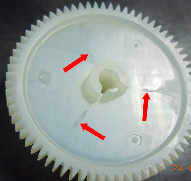
6.Welding Lines:
The Definition Of Burn Marks:
Weld Lines, or Knit Lines, occur when two or more independent melt fronts collide and fuse within the mold cavity. Visually, they appear as fine linear marks or notches on the surface; structurally, they often represent a localized area of mechanical weakness where the polymer chains have not fully entangled or diffused across the interface.
Solution To Welding Lines
ProductGeometry & Obstructions: Any functional feature such as a hole, core pin, or internal insert forces the melt stream to bifurcate. When the streams rejoin downstream of the obstacle, a weld line is inevitable. Non-uniform wall thicknesses also cause “race-tracking,” leading to unpredictable merging points.
Thermaland Pressure Loss: Low melt or mold temperatures cause the advancing “skin” of the plastic to solidify prematurely, preventing a homogeneous bond. Insufficient injection speed allows the fronts to cool before they meet.
Venting and Contamination: If air cannot escape at the junction, it acts as a pressurized buffer. Furthermore, excessive mold release sprays or lubricants can be “plowed” by the melt front and trapped at the interface, chemically preventing a molecular bond.
7.Air Bubble:
The Definition Of Air Bubble:
Air Bubbles, often referred to as Gas Traps or Blisters, are pockets of air or gas trapped within the polymer matrix. While they are major cosmetic failure in transparent materials like PC or PMMA, they also represent structural localized weaknesses.
Before troubleshooting, we must determine if the defect is a Air bubble or a Void (shrinkage).
- The Heat Test: Apply a localized heat source (like a torch) to the area.
- If it is a Bubble, the trapped gas will expand, causing the surface to swell or bulge.
- If it is a Vacuum Void, the localized plastic stock will collapse or sink inward as the material softens.
The Root Causes Of Air Bubble:
Bubbles are the result of gas being introduced into the melt stream or being unable to exit the cavity:
- Machine and Process Dynamics: * Low Back Pressure: If back pressure is insufficient, the melt is not properly compressed, allowing air to remain between the resin pellets as they move toward the screw tip.
- Excessive Decompression (Suck Back): Retracting the screw too far can pull ambient air into the nozzle, which is then “shot” into the cavity.
- Thermal Degradation: Overheating the resin causes it to break down, releasing gaseous byproducts.
- Tooling and Venting Deficiencies: If the mold’s venting system is clogged, too shallow, or crushed by excessive clamping force, the air displaced by the incoming melt has no escape route and becomes trapped within the part.
- Material Factors: The most common reason is Moisture Content. Hygroscopic resins (Nylon, ABS, PC) that are not properly dried will turn moisture into steam (“Water Vapor Blisters”) during the high-heat injection phase.
Solution To Air Bubbles
Eliminating bubbles requires a systematic check of material preparation and machine settings:
- Process Optimization:
- Increase Back Pressure: Set plastic pressure (typically 1000–2500 psi) to force air out of the pellet stream before it reaches the nozzle.
- Minimize Decompression: Reduce “suck back” to the absolute minimum required to prevent nozzle drool.
- Profiled Injection: Slower fill speeds give air more time to exit through the vents.
- Tooling Maintenance: * Vent Restoration: Clean vents regularly to remove “plate-out” (additive residue). Ensure vents are sized to material specs.
-
- Optimize Clamping: Reduce tonnage to the lowest safe level to allow the mold to “breathe” without flashing.
- Material: Strictly follow the resin manufacturer’s drying time and temperature.
Leak Detection: Inspect water lines for microscopic cracks that could allow moisture to seep into the barrel or cavity.
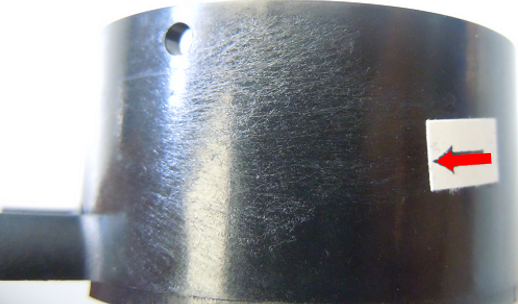
8.Silver Streaks(Splay):
The Definition Of Silver Streaks (Splay):
also known as Splay or Silver Marks, are a common surface defect in injection molding. They appear as silvery or white splash marks that usually spread out from the gate area. These streaks follow the direction of the plastic flow and can make a high quality part look like a failure.
The Root Causes Of Silver Streaks
There are four main reasons why these marks appear during production:
- Moisture (The Most Common Cause): Many plastics (like ABS, Nylon, or PC) absorb water from the air. If the material is not dried well, this water turns into steam inside the hot machine. This steam is then forced to the surface of the part, creating shiny streaks.
- Air Entrapment: If the screw pulls back too far (excessive decompression), air can be sucked into the barrel. This air then mixes with the plastic and shows up as streaks on the next shot.
- Material Damage (Overheating): If the melt temperature is too high or the plastic stays in the hot barrel for too long, the polymer molecules break down. This “burning” process releases gas that causes splay marks.
- Contamination: Dust, oil from ejector pins, or leftover plastic from a previous run can cause streaks. Even small amounts of grease can bleed onto the mold surface and ruin the finish.
Solution To Silver Streaks
- Correct Pre-drying: Always dry materials like PC or Nylon according to the manufacturer’s instructions.
- Keep it Clean: Keep material containers closed to prevent dust and moisture from getting in.
- Increase Back Pressure: This is a key trick. Higher back pressure helps compress the melt and push out air trapped between the plastic pellets before it reaches the nozzle.
- Manage Temperatures: If the plastic is burning, lower the barrel temperature. Also, reduce the screw speed (RPM) to lower “shear heat.”
- Optimize Speed: Slow down the injection speed to give air more time to escape through the vents.
- Improve Venting: Add or enlarge vents so that steam and gas can escape easily.
- Gate Modification: If the gate is too small, it creates too much friction. Enlarging the gate helps the plastic flow more smoothly.
- Regular Cleaning: Clean the mold surface and ejector pins regularly to remove grease or residue.
Conclusion:
Understanding these eight major injection molding defects,from Sink Marks to Silver Streaks is the first step toward a successful project, At Qlution Mold, our philosophy is simple: The best way to fix a defect is to prevent it from ever happening, we identify potential risks in your product’s geometry long before the mold is built. Whether it’s optimizing wall thickness to prevent warpage or strategically placing gates to hide weld lines, we ensure your parts are born perfect.