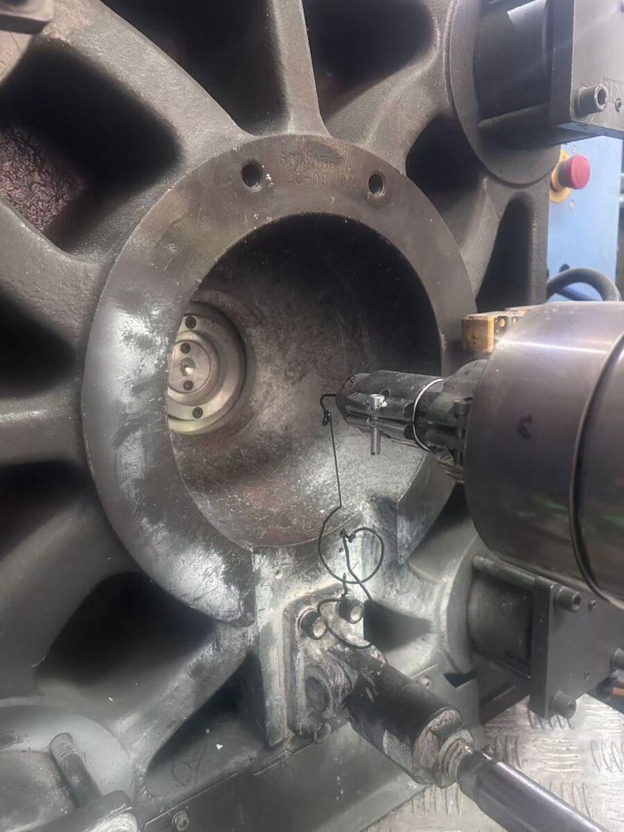
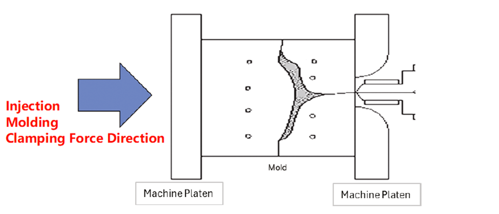
Injection molding clamping force is used to counteract the immense internal pressure generated when molten plastic is injected into the mold cavity. During the injection phase, the high-pressure plastic exerts a significant “separating force” on the mold faces that can easily force the mold halves apart.To maintain the integrity of the part and prevent defects like “flash” (leaking plastic), the clamping mechanism must provide a superior opposing force to keep the mold securely locked. This maximum capacity is known as the machine’s tonnage, a value typically measured in tons.
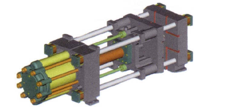
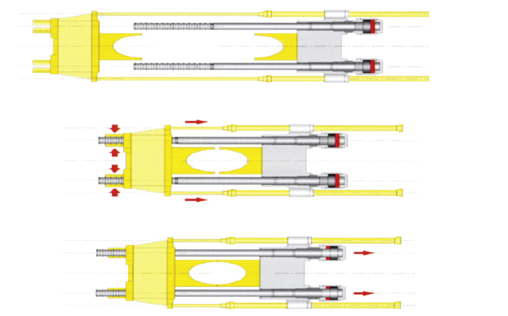
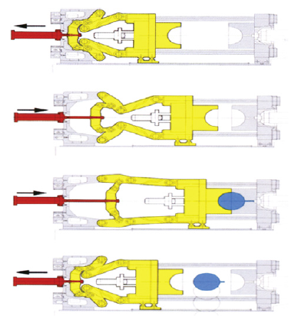
- Mechanical toggle clamping systems: Known for their speed and energy efficiency
- Hydraulic clamping systems: Valued for their precise force control and flexibility
- Hydraulic two-stage piston systems: Designed to combine high-speed movement with high-force locking.
- Tiebar-less systems: Ideal for large or complex molds, offering unobstructed access to the platens.
- Electric systems: Favored for high-precision applications and cleanroom environments due to their cleanliness and repeatability.
How to Calculate Injection Molding Clamping Force: A Step-by-Step Guide.(Clamping force formula injection molding)
Fc =injection pressure * projected area of the part
For example, assuming a projected area of 64.5 cm2 (10 in.2) and an assumed injection pressure of 35,000 kPa (5,000 psi) necessary to fill the cavity, the required clamping force will be
64.5 cm2 · 35,000 kPa ÷10,000 = 225 kN
(or 10 in.2 · 5,000 psi = 50,000 lb = 25 tons)
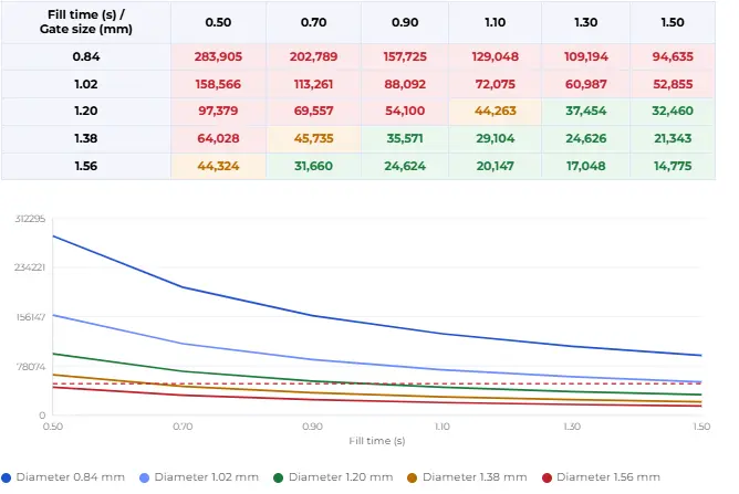
Theoretical Injection Pressure Graph

| Speed | 1 mm/s= 0.0394 in/s 1 in/s= 25.4 mm/s |
| Pressure | 1 psi= 0.0069 MPa 1 psi= 0.0690 bar 1 bar= 14.50 psi 1 bar= 0.1 MPa 1 MPa= 145.04 psi 1 MPa= 10 bar |
| Temperature | °Fahrenheit=(1.8x°Centigrade)+32 Example:50°C=(1.8×50)+32=122°F °Centigrade=(°Fahrenheit-32)/ 1.8 Example:200°F=(200-32)/1.8=93.3℃ |
| Weight | 1 ounce(oz)= 28.35 g 1 gram(g)= 0.035 oz |
| Tonnage | 1 kN= 0.11 US tons 1 kN= 0.1 metric ton 1 US ton= 9.09 kN 1 US ton= 0.909 metric tons 1 metric ton= 10 kN 1 metric ton= 1.1 US tons |
In a standard 2-plate configuration, the runner system exists on the same parting line as the cavities. Therefore, the injection pressure acts upon the entire surface area of both.
Large Parts: The runner area is often negligible compared to the cavity area. However, it should still be accounted for to ensure sufficient safety factors.
• Small/Precision Parts: The runner system can equal or even exceed the projected area of the cavities themselves. In these cases, failing to include the runner area will result in an underestimation of the required tonnage, leading to flash or tool damage.
Because 3-plate molds utilize multiple parting lines, the runner system and the cavities typically occupy different planes.Standard Rule: In most applications, the projected area of the cavities is significantly larger than that of the runners. Consequently, clamping force calculations are usually based solely on the sum of the cavity areas.
The Exception: For micro-molding or extremely small components where the runner network is disproportionately large, you must identify which plane has the largest total projected area. If the runner system’s area exceeds the total cavity area, use the runner area as the primary value for clamping force calculations
Tonnage Selection: Why Your Press Capacity Matters More Than You Think
In injection molding production, choosing the appropriate press capacity is far more than simply finding a “large enough” machine. In fact, the selection of press capacity directly affects the lifespan of the mold, the dimensional accuracy of the products, and the energy efficiency of production. Many novice engineers tend to use press machines with much larger capacities than what is needed, believing that this is safer. However, this approach often backfires, leading to a series of hidden production problems.
First, we need to understand the concept of “tonnage utilization rate”. Ideally, the locking force required for production should fall within 20% to 80% of the machine’s rated tonnage. If the tonnage is chosen to be too large (for example, using a 400-ton machine to produce a part that only requires 50 tons of locking force), due to the uneven distribution of pressure, the central area of the mold will be subjected to extremely high local stress. This phenomenon will cause the template to undergo a slight “central depression” deformation. Long-term operation will not only collapse the parting surface of the mold but also damage the parallelism of the machine’s template. Moreover, an excessively large tonnage will squeeze out the necessary exhaust gaps within the mold, preventing the gas from being expelled, thereby causing gas entrapment, burning, or product glue deficiency.
Conversely, if the tonnage is chosen to be too close to the upper limit, the tie bars of the machine will be in a state of extreme stretching. During continuous production, changes in material batches or fluctuations in mold temperature can cause a sudden increase in pressure. Once this exceeds the limit, the mold will “open its mouth”, resulting in severe flash marks. From a cost perspective, the energy consumption, hydraulic oil consumption, and maintenance costs of large machines are much higher than those of small machines. Therefore, a scientific tonnage selection requires us to obtain precise requirements through mold flow analysis (Moldflow) or calculation, and choose the most suitable machine. This not only protects your assets (molds and machines) but also significantly enhances your market competitiveness by optimizing the cycle time and reducing energy efficiency costs. As professional mold manufacturers, we always recommend that customers conduct an accurate tonnage matching assessment at the project initiation stage, which is the cornerstone for achieving long-term stable production.
Machine Inputs vs. Process Outputs: The Advanced Technician’s Mindset
This is the definitive line that separates a standard operator from an advanced technician. we must shift our focus from “Machine Inputs” to “Process Outputs”. “When you type “200 Tons” into the control panel, that is merely a command—an Input. However, the actual pressure the plastic feels inside the cavity, along with the reactionary force exerted by the mold as it thermally expands against the machine, constitutes the true Output. As an advanced technician, I pay much closer attention to the strain monitoring on the Tie Bars. If the four tie bars are not loaded evenly, the total tonnage might look correct on the screen, but your part dimensions will fluctuate due to an imbalanced cavity pressure distribution.
Conclusion:
Selecting the correct tonnage is a critical balance between protecting your mold investment and ensuring part quality. While understanding the underlying formulas is essential for any professional, manual calculations can be time-consuming and prone to error.
To simplify your design process, we have developed a comprehensive Online Injection Molding Clamping Force Calculator. This interactive tool allows you to switch between Imperial and Metric units and apply different calculation methods including wall thickness and injection pressure variables.to get a precise estimate in seconds.
Don’t leave your production to guesswork. Try our calculator now to optimize your machine selection!