In plastic injection molding, the smallest details often decide the fate of multi-million dollar projects. Gate selection is one of those details. A gate too small triggers shear stress and material degradation. Poor placement creates weld lines, trapped air, or warpage that no amount of post processing can fix. A well designed gate, on the other hand, ensures balanced filling, consistent packing, and a clean finish.eliminating costly rework from the start.
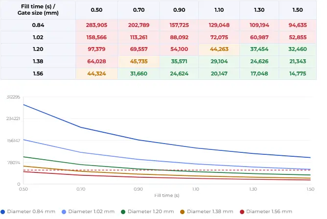
How much shear is actually too much depends on the resin and the gate geometry, not a single fixed number. We break down how to calculate gate shear rate and why the textbook “limits” shift case by case.
Whether you’re using submarine gates for automated production or valve gates for tight tolerances, understanding the fluid dynamics behind each gate type is what separates good tooling from great tooling. This guide goes beyond definitions. We’ll dissect gate physics, compare real world applications, and give you a troubleshooting framework to catch defects before the first shot.
Fundamental Principles of Injection Molding Runner and Gate Design
Effective gate design begins with one rule: place the gate at the thickest wall section. This maintains packing control and prevents sinks and voids from forming as the part cools.
Runner system selection follows part geometry. A standard two-plate cold runner works well for perimeter gating. Three-plate and hot runner systems are better suited for interior gating where the gate must be hidden or automatically removed.
Flow balance is equally critical. Long parts benefit from end gating, which creates a linear flow front and minimizes warpage from anisotropic shrinkage. Symmetrical 3D shapes call for centroid gating to produce a balanced, radial fill. In both cases, the melt must impinge on a cavity wall upon entry not shoot across open space to prevent jetting.
Finally, gate positioning should always account for venting. Trapped gas has to go somewhere. Place gates so air can escape at the parting line, and you’ll avoid burn marks and short shots before they start.
A Deep Dive into Injection Molding Gate Types: From Edge to Submarine
Direct Gate (Sprue Gate)
The Direct Gate also called a Sprue Gate is the simplest gating configuration: no runner system, just a direct path from the sprue into the cavity. This makes it ideal for single cavity molds producing cylindrical or symmetrical parts such as buckets, tubs, helmets, and cups.
The central placement of a direct gate means the melt enters the cavity with minimal loss of temperature or pressure. The feed bore is conical, widening as it approaches the cavity to maintain flow velocity.
One non-negotiable principle applies here, as it does with every gate type: the part wall must be at its thickest at the gate location and taper gradually along the flow path. This prevents premature freeze off and ensures the cavity packs out completely.
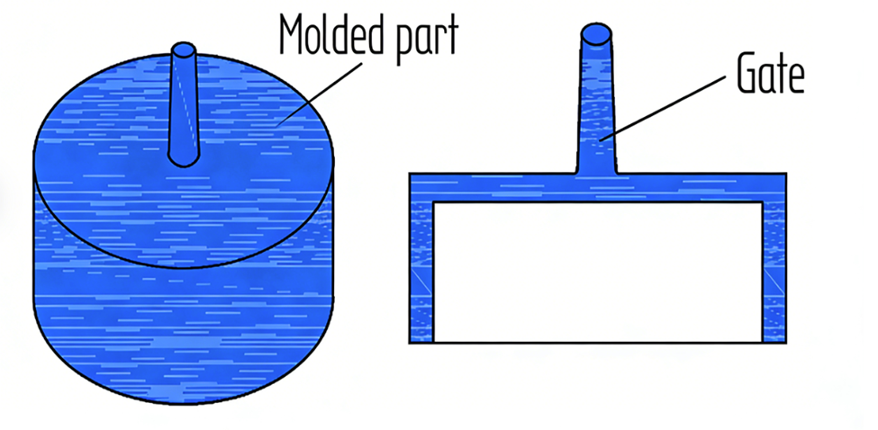
The diameter of the Sprue gate can be determined according to below reference
| Weight molded part in g | Direct gate in mm |
| 0.5-10 | 2.5-3.5 |
| 10-20 | 3.5-4.5 |
| 20-40 | 4.0-5.0 |
| 40-150 | 4.5-6.0 |
| 150-300 | 4.5-7.5 |
| 300-500 | 5.0-8.0 |
| 500-1000 | 5.5-8.5 |
| 1000-5000 | 6.0-10.0 |
Not sure which gate type works best for your part? Our prototype tooling service lets you test real shots in 7–15 days ,so you can validate gate location and design before committing to production tooling.
Pinpoint Gate
The Pinpoint Gate is the standard restricted gate for three plate cold runner molds. The runner sits on a secondary parting line and the cavity sits on the primary. When the mold opens, the gate tears away from the part automatically and no secondary operation required.
For this to work cleanly, the gate must be small enough to break without damaging the part, and tapered so the break occurs at the narrowest cross-section. In many designs, the part wall is intentionally dimpled to recess any remaining vestige flush with the surface.
Dimensioning follows a straightforward guideline: gate diameter should be 40–50% of the wall thickness, with a gate length of 0.5 to 1.0 mm.
Tunnel Gate
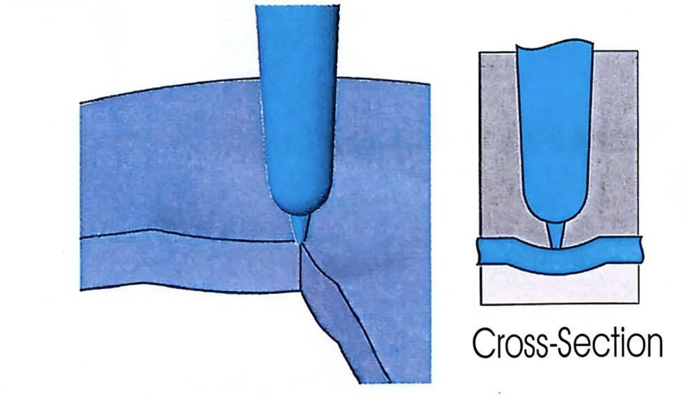
The Tunnel Gate is one of the most widely used gating systems in two plate cold runner molds and for good reason. It combines automatic degating with a clean, hidden gate location, all within a standard mold configuration.
The gate tunnels from the runner to the cavity below the parting line through an inclined bore. During ejection, the gate shears away from the part as it’s pulled through the tunnel. No manual trimming. No secondary fixtures. The gate tip is conical with its smallest end attached to the part, ensuring a controlled break.
Key design constraints:
For brittle materials, increasing gate body thickness keeps it warmer and more flexible
Gate tip diameter: typically 40–70% of part wall thickness
Material must be ductile enough to distort during ejection
Cashew or Banana Gate
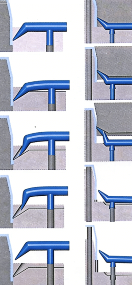
The Cashew Gate also called a banana gate or whip gate is a tunnel gate taken to its logical extreme. Where a standard tunnel gate is limited by straight-line geometry, the cashew gate curves, allowing the injection point to reach locations that are completely hidden from view: the underside of a part, an interior surface, or through the mold core itself.
This capability comes at a cost. The curved geometry requires the gate material to undergo significant distortion during ejection. That limits material selection to tough, flexible plastics with high ductility. Fiber reinforced materials glass or mineral filled are off the table entirely.
| Plastic material | MINIFLOW | GTR/GTE 10mm | GTR/GTE 12mm | GTR/GTE 14mm |
| Polyolefin Polyamide (PE,P, PA, etc.) | L=17-20 | L=20-25 | L= 22-27 | L= 24-30 |
| Styrenic based materials (ABS, ASA, etc.) | L= 22-27 | L = 25-27 | L=27-32 | L=30-35 |
| Thermoplastic Elastomer (TPE) Polyurethane (TPU) | L=15-20 | L= 15-25 | L = 17-27 | L=20-30 |
| PA + PF POM | L=25-30 | L=30-35 | L=32-37 | L=35-40 |
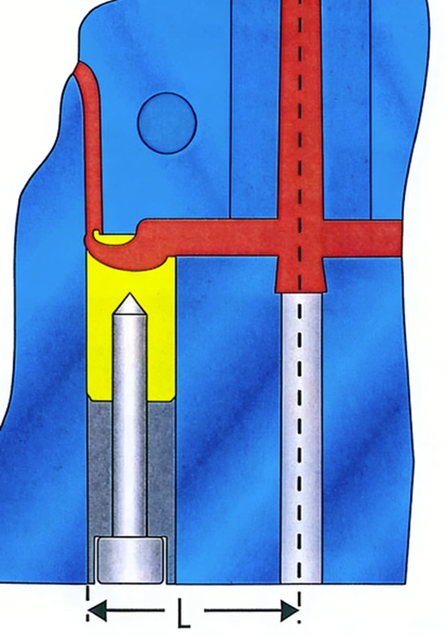
For successful implementation, the material must possess excellent ductility at the time of ejection. If a less ductile material is used, its flexibility can be enhanced by increasing the cross-sectional area of the gate body, ensuring it remains hotter during the ejection cycle. This strategy is particularly effective for amorphous materials, which feature a broad solidification temperature range. Given the intricate geometry involved, many manufacturers opt for specialized, powder-injection-molded gate inserts, such as those from EXAflow, which include side-wall relief to thermally insulate the gate from the cooled mold. This insulation keeps the gate warmer and more pliable, further assisting the ejection process.The ejection mechanism for a cashew gate requires precise engineering; an ejector pin must be positioned close to the “whip” to lift the gate, allowing the molded part to effectively “unscrew” itself during ejection. Additionally, because these gates do not always tear off cleanly, the cutting location should be recessed or deepened within the molded part. This design prevents any remaining gate protrusion from interfering with the part’s aesthetic or functional surface.
Ring Gate
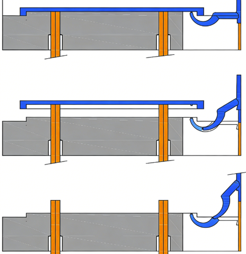
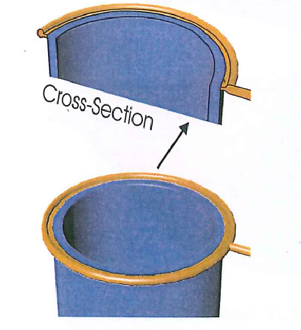
Ring Gates are functionally film gates that have been wrapped circumferentially around a cavity. Primarily utilized for cylindrical components in two-plate cold runner molds, the strategic objective of a ring gate is to eliminate weld lines, ensure a uniform flow front, and provide robust resistance against core deflection. Despite these theoretical advantages, the implementation of ring gates presents significant practical challenges, including complexities in manual degating and a tendency toward highly unpredictable or unbalanced flow, like the characteristics observed in standard film gates.
To achieve successful outcomes, mold filling analysis with precisely modeled gate geometry is essential to predict potential flow anomalies. While variations such as edge or tunnel gates can be integrated to facilitate automatic degating, these modifications often compromise flow symmetry, leading to diminished concentricity or induced core deflection. Standard designs frequently seen in the industry may result in unbalanced filling; therefore, a preferred gating arrangement often requiring advanced melt rotation technology should be employed to optimize fill balance. It must be noted, however, that utilizing multiple gate entries to solve balance issues will inevitably introduce multiple weld lines, which may impact the part’s structural or aesthetic integrity.
Regarding dimensional specifications, ring gates adhere to the same general engineering guidelines as film gates. The optimal manifold diameter is determined by a complex interplay of variables, including the specific rheological properties of the polymer, the part’s mass and dimensions, and the total required flow length.
Film Gate
Film Gates, or flash gates, are designed to provide the benefits of a fan gate such as broad melt distribution while significantly reducing the space and material required within the mold. In this configuration, a runner connects to a gate manifold that distributes the polymer melt along a wide, thin gate land attached directly to the part.
Despite its compact design, the film gate presents certain challenges in flow predictability compared to the fan gate. The melt often exhibits a tendency to hesitate at the thin gate land closest to the runner feed point. This behavior causes the melt to “race” down the gate manifold and enter the cavity further away from the initial feed point.
Key operational considerations for Film Gates include:
Fill Rate Optimization: Film gates perform most effectively at fast injection rates, which help minimize melt hesitation at the gate land.
Process Sensitivity: The resulting filling patterns are highly sensitive to variations in the injection process.
Reversing Flow Imbalance: Increasing the injection rate can potentially counteract the tendency of the melt to bypass the initial feed area.
Conclusion:
The gate types covered in this guide each solve a different problem. The real skill is knowing which problem you actually have. Material, geometry, volume, and quality tolerance all pull in different directions, and the best gate for your part is the one that resolves those tensions with the least compromise.
If you are still working through the decision for your next tool, we are happy to take a look. Send us your part design and we will tell you what we think.