In plastic injection molding, the smallest details often dictate the success of multi-million-dollar projects. At the heart of this is the gate–the critical intersection where design meets reality. Choosing a gate is a high-stakes balancing act: a gate too small can trigger shear stress and material degradation, while poor placement leads to unsightly weld lines, trapped air, or catastrophic warpage. Conversely, a well-engineered gate ensures balanced filling, consistent packing, and a seamless finish, eliminating the need for costly manual post-processing. Whether you are utilizing submarine gates for automation or valve gates for precision, understanding the fluid dynamics of each type is essential. This comprehensive guide moves beyond the basics to dissect gate physics, compare real-world applications, and provide a troubleshooting framework to eliminate defects before the first shot. If you aim to optimize cycle times and elevate part quality, you are in the right place.
Fundamental Principles of Injection Molding Runner and Gate Design
The core of effective runner and gate design lies in balancing mold complexity with material behavior to ensure structural and aesthetic integrity. Optimal design requires placing gates at the thickest wall sections to maintain packing control and prevent defects like sinks or voids, while selecting a runner system—such as a standard two-plate cold runner for perimeter gating or three-plate and hot runner systems for interior gating—that suits the part’s geometry. To minimize warpage and residual stress caused by anisotropic shrinkage, long parts should utilize end-gating for linear flow, while 3D symmetrical shapes benefit from centroid gating to create a balanced radial flow. Furthermore, designers must ensure the melt impinges on a cavity wall upon entry to prevent jetting, manage flow lengths to control clamp tonnage and core deflection, and strategically position gates to allow for proper venting at the parting line, thereby mitigating gas traps and ensuring a high-quality finish.
A Deep Dive into Injection Molding Gate Types: From Edge to Submarine
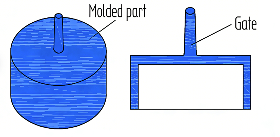
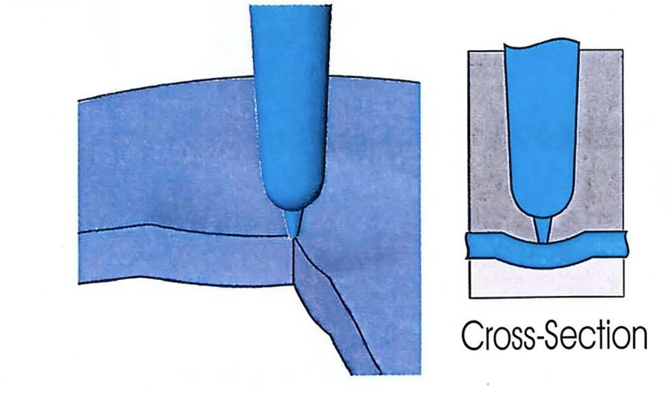
Direct Gate (Sprue Gate)
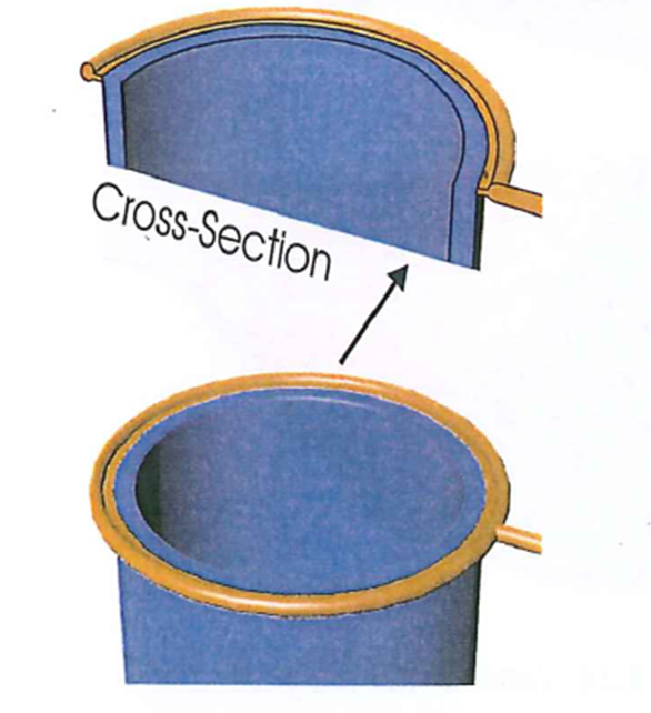
In the diverse landscape of gating options, the Direct Gate (also known as a Sprue Gate) occupies a unique position as a design where there is no traditional runner system; instead, the part is gated directly from the sprue. This configuration is the hallmark of single-cavity molds, allowing for the direct and central delivery of the polymer melt into the mold cavity, which is ideal for many cylindrical or symmetrically shaped parts such as buckets, tubs, helmets, cups, and disk-shaped parts. The defining feature of a direct gate is its central placement, which ensures the melt flows into the cavity virtually without loss of temperature or pressure. Structurally, the bore hole for the melt feed within the bushing is conical, widening as it progresses toward the mold cavity. A fundamental principle for direct gating—as with all gate types—is ensuring the molded part’s wall thickness is at its maximum at the gate location and gradually decreases along the flow path to prevent premature gate freeze-off and ensure the cavity is properly packed. In practice, the thickest part of the direct gate is calculated by taking the average wall thickness of the molded part and adding a 2.0 mm safety factor. While the direct gate offers superior pressure transmission, it necessitates mechanical post-processing as the sprue must be subsequently removed through cutting or milling, which leaves a visible gate vestige. Although designers may opt for a heated gate nozzle with a pinpoint gate to eliminate this rework, such an alternative introduces a small pressure loss that must be carefully considered when optimizing the injection process.
The diameter of the Sprue gate can be determined according to below reference
| Weight molded part in g | Direct gate in mm |
| 0.5-10 | 2.5-3.5 |
| 10-20 | 3.5-4.5 |
| 20-40 | 4.0-5.0 |
| 40-150 | 4.5-6.0 |
| 150-300 | 4.5-7.5 |
| 300-500 | 5.0-8.0 |
| 500-1000 | 5.5-8.5 |
| 1000-5000 | 6.0-10.0 |
Pinpoint Gate
In the architecture of three-plate cold runner molds, the Pinpoint Gate serves as a specialized restricted gate where the runner system is situated on a secondary parting line while the part cavity resides on the primary parting line. This design allows the gate to be automatically torn away from the part wall during mold opening, a process that requires the gate diameter to be small enough to break cleanly without damaging the component. To ensure the break occurs at the smallest cross-section and to minimize gate vestige, the gate must be tapered. In many applications, the part wall is intentionally dimpled to recess any remaining vestige, ensuring a flush aesthetic finish. The dimensions of a pinpoint gate are critical, like all restrictive tear gates, the diameter should typically be approximately 40% to 50% of the wall thickness, with a length ranging from 0.5 to 1 mm. Structurally, a central pinpoint gate is constructed with a relatively large pre-chamber and a small tapered end, typically not exceeding 0.8 to 1.0 mm in both diameter and height. The dimensioning of this pre-chamber is crucial for successful injection molding, as an undersized chamber risks premature solidification of the melt. While this gating method is particularly suitable for high-speed production with short cycles of 3 to 4 shots per minute, it is generally restricted to relatively simply designed molds. Typical applications for pinpoint gates include thin-walled or symmetrical items such as cups, buckets, bowls, boxes, and various packing materials.
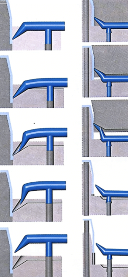
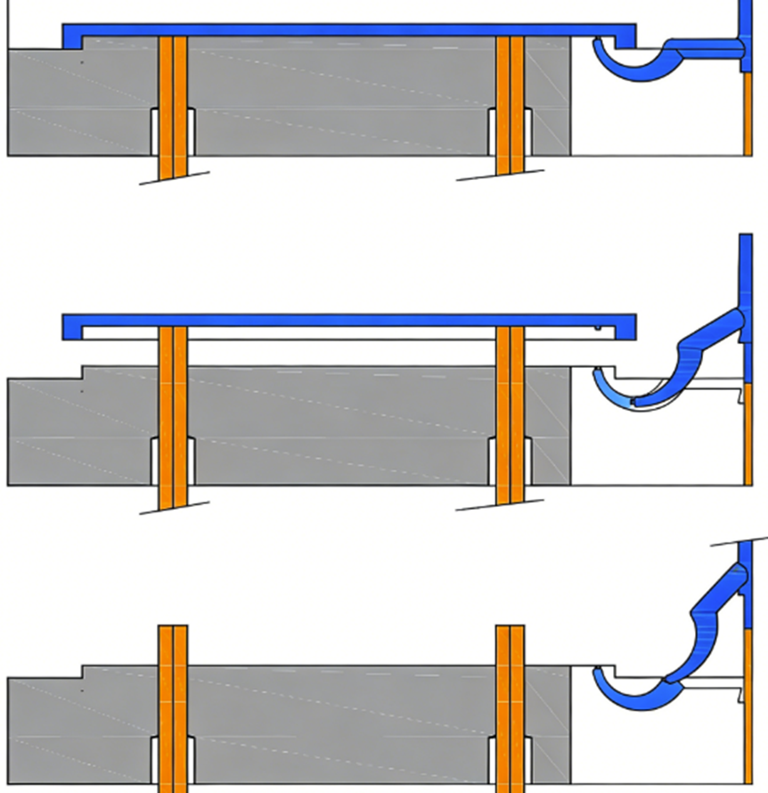
Tunnel Gate
The Tunnel Gate, also widely known as a Submarine Gate, is a highly popular and cost-effective gating system designed to provide automatic degating in standard two-plate cold runner molds. The gate is engineered to “tunnel” from the runner system to the cavity below the mold’s parting line through an inclined, tunnel-like bore hole. During the ejection phase, the gate is automatically sheared or torn away from the molded part as it is pulled through the tunnel, eliminating the need for manual post-processing. Structurally, the gate is typically conical, with its smallest end attached to the part to ensure a clean break. Depending on the design, the transition into the part may appear oval or crescent shaped. A superior design variation involves the use of a “conical bucket gate,” which serves to trap the initial “cold plug” of the melt, allowing only the hot plastic core to enter the cavity.
While automatic degating is a primary advantage, it introduces specific design constraints. The gate opening must be small enough to break without damaging the part or leaving excessive vestige, yet large enough to prevent over-shearing of the material or premature freeze-off, which can hinder proper packing. Typically, gate-tip diameters vary between 40% and 70% of the part’s wall thickness, though this remains dependent on the specific material and application. Because the gate and runner must distort during retraction from the tunnel, this system is preferred for materials that are not overly brittle. However, designers can accommodate more brittle materials by increasing the thickness of the gate’s main body, keeping it warmer and more flexible during ejection.
Variations in the gate tip design, such as the D-shaped opening, can further optimize the process. Although a standard conical tip is most common, the D-shaped design can improve packing—particularly for semi-crystalline materials—and reduce gate vestige by insulating the flowing melt from the cold steel at the bottom of the gate tip. The trade-off for these advanced designs includes increased difficulty in maintaining consistent gate sizes across multi-cavity molds and a higher susceptibility to wear, which may eventually lead to gate-size variations between cavities.
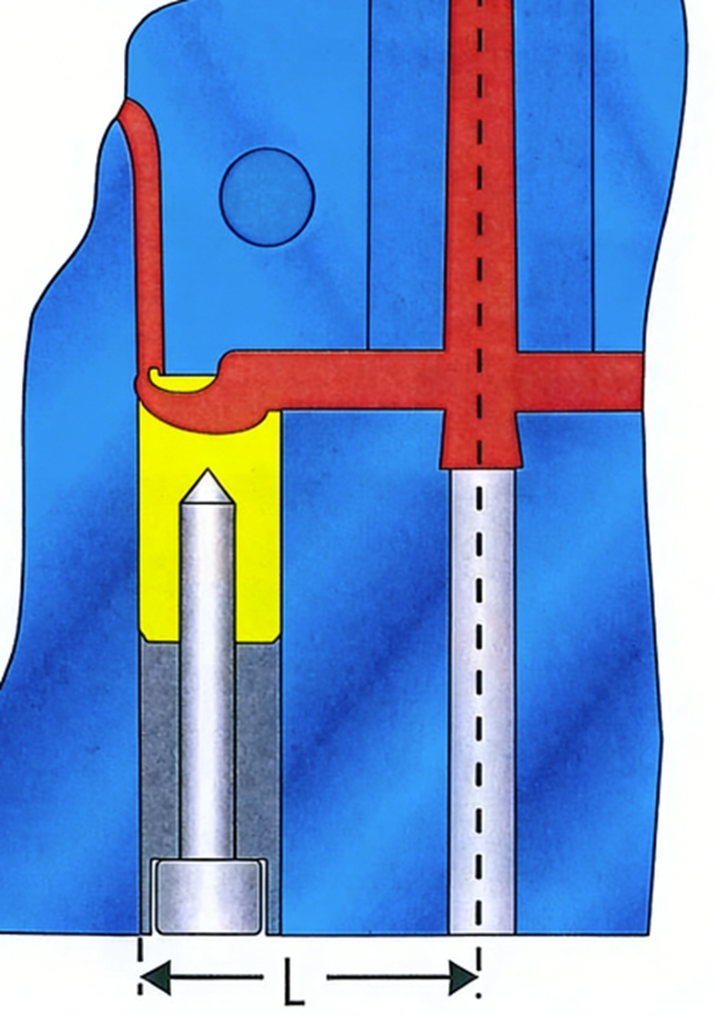
Cashew or Banana Gate
Cashew gates, also frequently referred to as banana gates or whip gates, are a sophisticated variation of tunnel gates designed to reach gating locations that are inaccessible to standard tunnel gate configurations. These gates are exclusively utilized when the injection point must be completely hidden from view, often gating into the underside or interior of a part through the mold core—a process considered an expensive and technically demanding mold solution. Because the complex curved geometry requires the gate material to undergo significant distortion during ejection, this system is strictly limited to tough, flexible plastics with high ductility. Consequently, these gates cannot be used with materials reinforced by mineral or glass fibers.
| Plastic material | MINIFLOW | GTR/GTE 10mm | GTR/GTE 12mm | GTR/GTE 14mm |
| Polyolefin Polyamide (PE,P, PA, etc.) | L=17-20 | L=20-25 | L= 22-27 | L= 24-30 |
| Styrenic based materials (ABS, ASA, etc.) | L= 22-27 | L = 25-27 | L=27-32 | L=30-35 |
| Thermoplastic Elastomer (TPE) Polyurethane (TPU) | L=15-20 | L= 15-25 | L = 17-27 | L=20-30 |
| PA + PF POM | L=25-30 | L=30-35 | L=32-37 | L=35-40 |
For successful implementation, the material must possess excellent ductility at the time of ejection. If a less ductile material is used, its flexibility can be enhanced by increasing the cross-sectional area of the gate body, ensuring it remains hotter during the ejection cycle. This strategy is particularly effective for amorphous materials, which feature a broad solidification temperature range. Given the intricate geometry involved, many manufacturers opt for specialized, powder-injection-molded gate inserts, such as those from EXAflow, which include side-wall relief to thermally insulate the gate from the cooled mold. This insulation keeps the gate warmer and more pliable, further assisting the ejection process.The ejection mechanism for a cashew gate requires precise engineering; an ejector pin must be positioned close to the “whip” to lift the gate, allowing the molded part to effectively “unscrew” itself during ejection. Additionally, because these gates do not always tear off cleanly, the cutting location should be recessed or deepened within the molded part. This design prevents any remaining gate protrusion from interfering with the part’s aesthetic or functional surface.
Ring Gate
Ring Gates are functionally film gates that have been wrapped circumferentially around a cavity. Primarily utilized for cylindrical components in two-plate cold runner molds, the strategic objective of a ring gate is to eliminate weld lines, ensure a uniform flow front, and provide robust resistance against core deflection. Despite these theoretical advantages, the implementation of ring gates presents significant practical challenges, including complexities in manual degating and a tendency toward highly unpredictable or unbalanced flow, like the characteristics observed in standard film gates.
To achieve successful outcomes, mold filling analysis with precisely modeled gate geometry is essential to predict potential flow anomalies. While variations such as edge or tunnel gates can be integrated to facilitate automatic degating, these modifications often compromise flow symmetry, leading to diminished concentricity or induced core deflection. Standard designs frequently seen in the industry may result in unbalanced filling; therefore, a preferred gating arrangement—often requiring advanced melt rotation technology—should be employed to optimize fill balance. It must be noted, however, that utilizing multiple gate entries to solve balance issues will inevitably introduce multiple weld lines, which may impact the part’s structural or aesthetic integrity.
Regarding dimensional specifications, ring gates adhere to the same general engineering guidelines as film gates. The optimal manifold diameter is determined by a complex interplay of variables, including the specific rheological properties of the polymer, the part’s mass and dimensions, and the total required flow length.
Film Gate
Film Gates, or flash gates, are designed to provide the benefits of a fan gate—such as broad melt distribution—while significantly reducing the space and material required within the mold. In this configuration, a runner connects to a gate manifold that distributes the polymer melt along a wide, thin gate land attached directly to the part.
Despite its compact design, the film gate presents certain challenges in flow predictability compared to the fan gate. The melt often exhibits a tendency to hesitate at the thin gate land closest to the runner feed point. This behavior causes the melt to “race” down the gate manifold and enter the cavity further away from the initial feed point.
Key operational considerations for Film Gates include:
Fill Rate Optimization: Film gates perform most effectively at fast injection rates, which help minimize melt hesitation at the gate land.
Process Sensitivity: The resulting filling patterns are highly sensitive to variations in the injection process.
Reversing Flow Imbalance: Increasing the injection rate can potentially counteract the tendency of the melt to bypass the initial feed area.
The path to zero-defect manufacturing starts with a design that respects the complex physics of polymer flow. Whether you are battling gate blush in a Tunnel Gate or managing the unpredictable hesitation of a Film Gate, the principles outlined here provide the framework to navigate the high-stakes world of injection molding with precision and confidence.